Ronen Dolev | October 2026
A print can look perfectly acceptable while the structure beneath its surface is not. A camera may report correct registration and clean solids; a spectrophotometer may confirm the expected color. Neither observation necessarily establishes the thickness of a buried coating, the geometry of a transparent interface, or the location of a subsurface discontinuity. As printing extends into functional materials and complex laminates, this distinction becomes increasingly important.
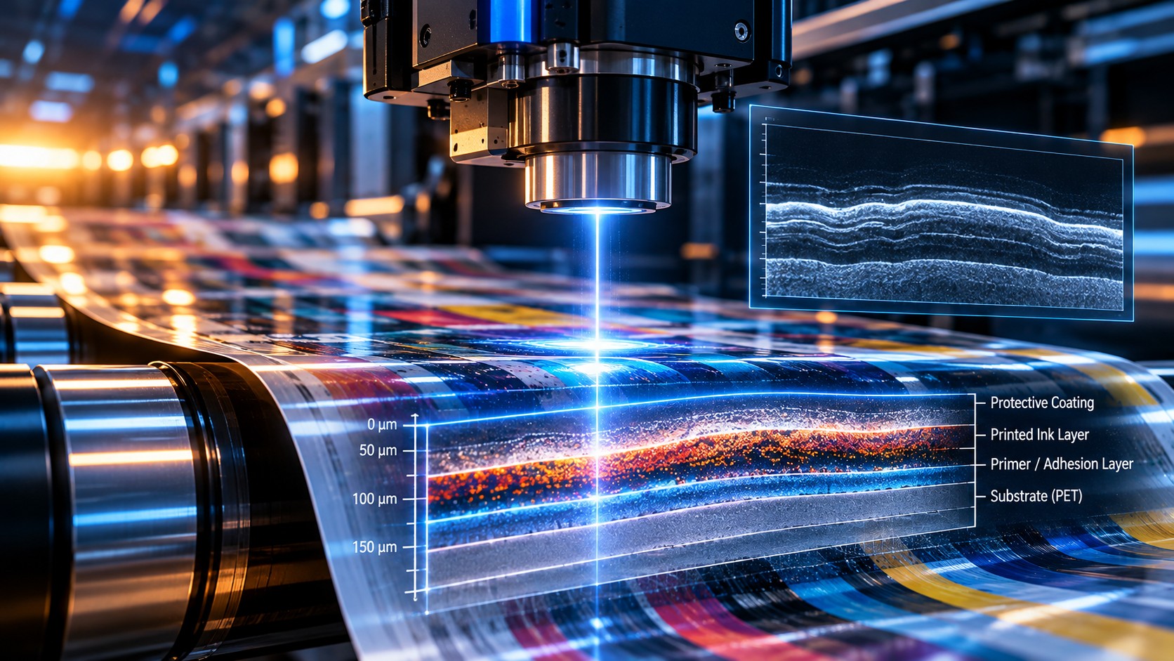
Optical coherence tomography (OCT) offers a different way to interrogate a printed product. Under suitable optical conditions, it can create depth-resolved images without cutting the sample. Research has already demonstrated OCT on printed electrodes, flexographically printed coatings, pharmaceutical films, and moving roll-to-roll materials. The interesting question for industrial printing is not whether OCT works in general—it does—but precisely where it adds reliable information, and where the physics prevents it from doing so. [1–7]
This article separates published experimental evidence from engineering interpretation. Its final section proposes a specific, as-yet-unperformed research program to evaluate OCT on liquid-electrophotographically printed structures. No results are claimed for that proposed LEP study.
1. From surface inspection to depth-resolved measurement
Industrial vision systems are exceptionally valuable for identifying missing print, registration errors, streaks, stains, and other visible defects. Optical-density and spectral measurements answer different questions about the light returned from an image. These approaches remain central to process control; they are simply not universal measures of internal structure.
OCT uses low-coherence interferometry. Light from a suitable broadband or swept source is directed toward the sample, and the returned signal is compared with a reference. The interference information allows reflections and scattering contributions to be located along the depth axis. A single depth profile is commonly called an A-scan; adjacent profiles can form a cross-sectional B-scan, and successive scans can be assembled into a three-dimensional data set.
A useful OCT image requires optical access. If an interface returns too little signal, or an overlying layer strongly absorbs or scatters the probing light, that interface may remain invisible. Reflective metallic structures can also obscure what lies beneath them. OCT therefore cannot be described as a camera that sees through every ink, foil, pigment, or laminate.
2. The metrology detail that changes the result
An OCT instrument measures optical path differences, not physical layer thickness directly. In a suitable normal-incidence approximation, physical thickness is obtained by dividing the measured optical path length through the layer by its group refractive index. The exact relationship depends on the optical system, geometry, and signal processing; multilayer samples may need additional modeling.
That distinction matters when the material changes. A transparent primer, a polymer substrate and a protective coating can differ in refractive index and dispersion. Treating an uncalibrated optical distance as an absolute thickness risks creating a precise-looking but inaccurate result. Cheng and Liu experimentally examined a scheme for determining thickness and refractive index together, using optical-glass reference specimens. Their work establishes the metrology principle; it is not a calibration certificate for printed ink. [8]
Three quantities should remain separate in any report: axial resolution, which concerns distinguishable features in depth; repeatability, which describes variation on repeated measurements; and measurement accuracy, which concerns agreement with a traceable reference. A quoted resolution of a few micrometers does not, by itself, guarantee that a similarly thin coloured ink layer can be measured accurately.
3. What published studies have actually demonstrated
Screen-printed electrodes moving under an OCT scanner
In Scientific Reports in 2013, Alarousu, AlSaggaf and Jabbour used spectral-domain OCT to inspect moving, screen-printed interdigitated electrodes in a simulated roll-to-roll arrangement. The researchers resolved selected structural properties at transport speeds up to approximately 1 m/min. The significance was demonstrating depth-aware inspection on moving printed objects, not claiming full-width inspection at modern industrial press speeds. [1]
Printed electronics and protective encapsulation
Jakub Czajkowski's 2013 doctoral research at the University of Oulu investigated OCT as a non-contact technique for printed electronics. It examined screen-printed conductors and insulators, printed color filters, coated structures and polymer encapsulation. The reported work also characterized protective layers approximately 1–2 µm thick using specialized optical arrangements. This is a valuable demonstration, but the layers, wavelengths and devices must be considered before extrapolating the result to other inks. A doctoral dissertation is an academic source, not itself a separate peer-reviewed journal article. [2]
Flexographic inks and coatings on flexible substrates
Sallese and colleagues reported research in 2022 on OCT characterization of inks and coatings deposited by flexography, focusing on flexible materials including PET-type films and paperboard. Unlike a broad theoretical discussion of imaging, this work directly addressed materials used by the printing industry. Its relevance lies in the feasibility of inspecting suitable deposited layers and interfaces, while its scope remains limited to the materials and equipment studied. [3]
Actual roll-to-roll measurement, beyond a simulated moving sample
A 2020 IEEE conference paper by Lauri, Liedert, Liedert and Fabritius reported OCT measurements of hot-embossed microchannel geometries in an actual roll-to-roll environment at 1 m/min. This measured surface and microchannel geometry rather than the internal thickness of a multicolor ink film. It nevertheless shows the type of synchronization and measurement arrangement that would be needed when a sample moves continuously. [4]
4. Evidence from very thin coatings—important but not interchangeable
OCT is not limited to printing research. In 2023, Wolfgang and colleagues published a high-resolution study of pharmaceutical multilayer coatings between about 5 and 50 µm thick. Their system achieved reported axial and lateral resolutions in air of 2.4 µm and 3.4 µm, respectively, allowing characterization of coating morphology and thickness variability under the reported conditions. [5]
In 2025, another study by Wolfgang and colleagues demonstrated real-time measurements of pharmaceutical coating thicknesses in the 2.5–20 µm range in an industrial process. Agreement with mass-based reference measurements was reported when agglomeration was negligible. The result is a meaningful example of in-process optical metrology; it does not establish that the same thickness range is attainable for opaque LEP inks on polymer films. [6]
Research on thermoplastic glass-fiber tapes provides another illustration of inline feasibility. Wenninger and co-authors examined moving reinforced tapes at speeds up to 15 m/min, using OCT to investigate defects and validate the results by microscopy. Their online publication appeared in 2024 and the journal issue in 2025. Those figures relate to a very different sample geometry, material, and inspection task; they cannot be adopted as throughput specifications for a label or packaging press. [7]
5. What OCT can and cannot tell a printer
Measurement question | OCT contribution | OCT contribution | Essential boundary | Essential boundary |
|---|---|---|---|---|
Is a transparent coating geometrically uniform? | May map depth and interface position when optical contrast and resolution permit. | May map depth and interface position when optical contrast and resolution permit. | Use known refractive indices and independent thickness references. | Use known refractive indices and independent thickness references. |
Is there a buried gap or structural discontinuity? | May reveal an interface or void that returns a separable optical signal. | May reveal an interface or void that returns a separable optical signal. | Not all voids or defects are optically detectable. | Not all voids or defects are optically detectable. |
Does a print meet color tolerances? | Not a substitute for a calibrated spectrophotometer. | Not a substitute for a calibrated spectrophotometer. | Spectral color and depth structure are different measurements. | Spectral color and depth structure are different measurements. |
Will a laminate adhere or seal correctly? | May supply structural clues for a failure investigation. | May supply structural clues for a failure investigation. | Cannot itself prove bond strength, seal performance or barrier properties. | Cannot itself prove bond strength, seal performance or barrier properties. |
Is an electrode electrically functional? | Is an electrode electrically functional? | May show some geometrical defects. | May show some geometrical defects. | Requires electrical continuity/resistance testing. |
A particularly important distinction is between detecting an unusual image feature and diagnosing its cause. A dark region in an OCT scan does not automatically prove delamination; it could arise from scattering, absorption, misalignment, or processing artifacts. Cross-sectional microscopy, profilometry, peel testing, electrical measurements or other methods may be needed to determine whether the anomaly matters.
6. Why LEP presents a separate research question
Liquid electrophotography forms a digitally controlled electrostatic image, develops it using charged liquid-ink particles and transfers the resulting image through an intermediate member before final transfer to the substrate. Public descriptions of LEP emphasize forming and transferring a thin ink film. The detailed optical response of the final print depends on the ink, colorant, substrate, and any finishing layers. [9]
The challenge for OCT is straightforward but consequential. If a printed ink film is thinner than the selected instrument's practical depth discrimination, the interfaces may not be separable. Absorbing pigments, scattering white inks, metallic films, reflective surfaces, and multilayer stacks may complicate interpretation. The apparent thickness of a signal feature cannot be assumed to equal the true thickness of the ink film.
The sources reviewed here did not identify a directly comparable, independently validated, peer-reviewed study that establishes OCT as a routine, calibrated inspection method for LEP ink films on a commercial press. That is an evidence gap, not evidence that the idea is impossible. The relevant scientific basis exists; application-specific feasibility and measurement uncertainty remain to be determined.
A more promising first investigation may involve a transparent or semi-transparent primer or coating associated with an LEP construction, rather than the coloured ink film itself. Even then, the interfaces must be shown to be optically resolvable and the measurement validated against independent references.
7. Implications for flexible packaging and functional printing
Flexible packaging can combine polymer films, surface treatment, printed color layers, adhesives and protective coatings. A structurally imperfect interface may contribute to a later failure, but it is essential not to confuse morphology with performance. An OCT scan does not measure oxygen transmission, water-vapor transmission, migration, coefficient of friction, lamination bond strength, or heat-seal resistance. Those properties require their own procedures.
OCT could become useful as an additional investigative measurement when the problem is fundamentally geometrical: a thickness transition, a patterned coating, a transparent layer, a microchannel, or a void at a sufficiently accessible interface. In printed electronics, it can complement—not replace—electrical characterization and mechanical durability testing. The operational question should always be: which failure mode is this measurement supposed to distinguish?
8. Inline inspection is a systems problem
A stationary laboratory scan can be valuable even if it will never operate at production speed. Inline deployment introduces another set of variables: web flutter, machine-direction motion, transverse scanning, vibration, encoder synchronization, standoff variation and scan-data volume. The measured field of view and inspection coverage must be reported alongside the transport speed; quoting only a meters-per-minute figure gives an incomplete picture.
Published moving-web work establishes feasibility for specific systems and samples. It does not guarantee full-web inspection, false-alarm performance or reliable defect detection at the speed of any existing LEP press. Before integrating OCT into production, a laboratory team should establish whether it can measure the intended property at rest; only then should it tackle synchronization and throughput.
9. Proposed future experiment: OCT characterization of LEP-printed layers
Research status: The following is an original proposed experimental program. It is not a description of a completed LEP trial, commercial qualification, or proven OCT capability.
Research question and hypotheses
The primary question is whether high-resolution OCT can resolve and quantify selected interfaces within LEP-printed and associated coated structures on flexible substrates, with an uncertainty acceptable for a clearly defined engineering decision. A second question asks whether any such capability remains stable when the material is transported under controlled motion.
The initial hypothesis is deliberately limited: on optically favorable LEP-related constructions, at least some layer boundaries—particularly transparent or semi-transparent coatings—may be distinguishable and measurable against an independent reference. A competing hypothesis is that pigment absorption, optical contrast, or insufficient axial discrimination will prevent meaningful measurement of the ink film itself. Both outcomes are scientifically useful.
Phase A — Build a reference sample set
The study should begin with approved, commercially permissible LEP inks and substrates, processed only in equipment configurations authorized by the manufacturer. The test set would include a transparent polymer reference, selected printed color patches, white and black patches when appropriate, and optional transparent primer or protective-coating constructions applied using approved processes. Control samples with no ink or coating would establish each substrate's baseline response. This OCT feasibility study does not require conductive research toner, machine alteration, or unapproved press operating conditions.
Rather than fixing unverified universal sample thicknesses, the investigators should prepare materials whose thickness can actually be measured by an independent method. Relevant process factors include colorant, nominal coverage or build, coating presence, and substrate optical properties. Material batches, sampling locations, processing history and environmental conditions should be traceable.
Phase B — Stationary optical feasibility and independent calibration
Acquire co-located OCT A-scans, B-scans and limited volumetric scans across each specimen. Record wavelength band, axial point-spread response, focus setting, signal-to-noise conditions, scan sampling, incidence geometry, and any image-processing assumptions. Where relevant, estimate or independently determine the group refractive index rather than treating optical depth as physical depth by default.
Compare OCT-derived interface locations and thicknesses with suitable independent techniques—for example, calibrated stylus or optical profilometry where a step geometry exists, and carefully prepared microscopy cross-sections for multilayer structures. Cross-section preparation should itself be checked for deformation. Repeated measurements by different operators and at different sample positions would quantify within-sample variation and method repeatability.
Phase C — Discriminating structural defects from optical artifacts
Prepare controlled variation specimens, such as deliberately varied transparent-coating build or documented interface structures, within approved material and processing limits. Evaluate whether OCT distinguishes actual structure changes from variations caused by surface texture, pigment absorption, multiple reflections, or focus. Record failure cases—not only successful images—and compare interpretation against independent reference data.
Phase D — Controlled motion, only after stationary success
If Phase B demonstrates a useful measurement, move selected specimens through a laboratory transport arrangement with measured web speed, tension, and standoff. Establish image registration and motion-induced error before attempting higher-speed acquisition. Published values of 1 and 15 m/min from unrelated studies may motivate test planning but must not be treated as target speeds or evidence of capability on an LEP line. Any later production trial would require separate safety, installation and equipment approvals.
Illustrative test matrix — proposed, not published results
Specimen family | Primary measurement question | Independent reference |
|---|---|---|
Unprinted transparent substrate | Can the substrate interfaces be resolved repeatably? | Supplier specification plus suitable independent thickness method |
Approved LEP color / black/white patches | Is ink-film geometry accessible, or obscured optically? | Cross-section, step-height or complementary microscopy where valid |
Transparent primer/coating on film | Can coating thickness or interface position be quantified? | Calibrated thickness and cross-sectional reference |
Coated printed construction | Can individual layer boundaries be distinguished? | Matched cross-section and documented construction |
Stationary versus moving reference | What error arises from motion, registration or flutter? | Known features, encoder log and repeated scans |
How the result should be judged
Success criteria should be defined before measurements are taken, based on the specific quality decision rather than an arbitrary claim of micrometer accuracy. At minimum, the team should report interface-detection rate, absolute or relative error against the independent reference, repeatability, reproducibility across specimens, coverage and measurement uncertainty. Confidence intervals and negative findings should accompany any claimed improvement. If limits cannot be met, the technology should not be described as qualified for that measurement.
The proposed program has three possible useful outcomes. First, OCT may prove suitable for selected coatings but not for the pigmented LEP film. Second, specialized OCT configurations might resolve some ink-related features but only under constrained conditions. Third, the method may be unsuited to the intended LEP geometry, while still providing value for offline coating analysis. None of those outcomes should be misrepresented as evidence of finished-product performance.
10. The next frontier is better questions, not more sensors
Optical inspection has already made industrial printing more measurable. OCT raises a different possibility: observing selected internal structures without destroying the sample. Published research provides a credible foundation, but the lesson is specificity. Different materials, thicknesses, and motion systems produced different capabilities, and the measurements were meaningful only within their validated conditions.
For LEP, the productive next step is a small, well-controlled metrology study—not an announcement that hidden ink defects can now be found on every press. If OCT can add reliable structural information for selected primers, coatings, or printed features, it may eventually complement color control, machine vision, adhesion studies, and functional testing. If it cannot, the negative result will still clarify where industrial print inspection should invest its attention.
The quality of a printed product increasingly depends on what the image alone cannot explain. The challenge is to measure that hidden structure with the same discipline that the printing industry already applies to color and registration.
Source notes and evidence classification
Evidence class | What can responsibly be stated |
|---|---|
Published experiments | OCT has been demonstrated on particular printed structures, coatings and moving manufactured materials under specified conditions. [1–7] |
Established measurement science | Depth reconstruction, refractive-index dependence, and measurement uncertainty are necessary considerations in OCT. [8] |
Documented LEP process | LEP forms and transfers a thin liquid-electrophotographic ink film through an intermediate transfer mechanism. [9] |
Original engineering proposal | An OCT study of selected LEP ink and coating constructions is plausible, but the proposed outcome is unverified. |
References
- Alarousu, E., AlSaggaf, A., & Jabbour, G. E. (2013). "Online monitoring of printed electronics by Spectral-Domain Optical Coherence Tomography." Scientific Reports, 3, 1562. DOI 10.1038/srep01562.
- Czajkowski, J. (2013). Optical Coherence Tomography as a Characterization Method in Printed Electronics. Doctoral dissertation, University of Oulu (academic thesis; not a standalone journal article).
- Sallese, M., Tabla, P., Morel, E., Mosquera Ortega, M., Fossati, J., & Torga, J. (2022). “Caracterización de electrónica impresa y recubrimientos por tomografía de coherencia óptica.” Revista Tecnología y Ciencia, 43, 52–62. DOI 10.33414/rtyc.43.52-62.2022.
- Lauri, J., Liedert, C., Liedert, R., & Fabritius, T. (2020). "Online quality assurance of microchannels in roll-to-roll by optical coherence tomography." IEEE International Instrumentation and Measurement Technology Conference (peer-reviewed conference paper). DOI 10.1109/I2MTC43012.2020.9128465.
- Wolfgang, M., et al. (2023). "Ultra-high-resolution optical coherence tomography for the investigation of thin multilayered pharmaceutical coatings." International Journal of Pharmaceutics, 643, 123096. DOI 10.1016/j.ijpharm.2023.123096.
- Wolfgang, M., et al. (2025). "Real-time monitoring of multiparticulate coating processes at industrial scale using ultra-high-resolution optical coherence tomography." International Journal of Pharmaceutics, 675, 125546. DOI 10.1016/j.ijpharm.2025.125546.
- Wenninger, M., et al. (2025 issue; online 2024). "Applying optical coherence tomography to inline quality monitoring of unidirectional glass-fiber-reinforced thermoplastic tapes." Journal of Thermoplastic Composite Materials, 38(8), 3051–3076. DOI 10.1177/08927057241259756.
- Cheng, H.-C., & Liu, Y.-C. (2010). "Simultaneous measurement of group refractive index and thickness of optical samples using optical coherence tomography." Applied Optics, 49, 790–797. DOI 10.1364/AO.49.000790.
- HP Indigo. "Liquid Electrophotography (LEP) Digital Printing Technology." Public manufacturer technology overview (industry process reference, not a peer-reviewed OCT study).
Further technical articles: ronendolev.com