Ronen Dolev | 2026
Industrial Printing, Materials, Applications & Color Science
Introduction - Does a New Press Architecture Change the Printed Product?
In digital printing, technological progress is often described as higher speed, more imaging stations, additional color channels, improved automation, or finer addressability. For a materials or process engineer, however, another question matters just as much: what has changed in the way an image is formed, an ink layer is assembled, and that layer is transferred to the substrate?
The development from conventional Liquid Electrophotography (LEP) to the LEPx architecture provides a particularly relevant case study. Both rely on electrostatic imaging, electrically charged ink particles, and indirect thermal transfer. Yet the methods for building a multicolor image differ significantly.
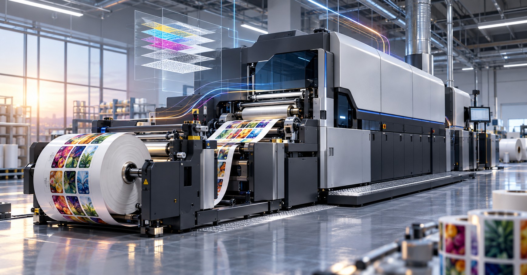
In the conventional HP Indigo LEP architecture considered here, a shared imaging engine produces color separations sequentially. In LEPx, as implemented in the HP Indigo V12, six imaging engines operate in parallel and transfer their separations to a common blanket belt. This changes the production architecture and the relationship between separations and press throughput.
It also raises engineering questions that cannot be answered by speed specifications alone. Do the ink-film properties remain equivalent? Can you achieve the same color target? Do coated papers, polymer films, and metalized substrates behave similarly? Are adhesion, opacity, gloss, or finishing performance affected?
The existence of a new architecture does not prove that any of those material properties improve or deteriorate. To evaluate the evolution responsibly, we must distinguish documented process physics, published machine design, and measured finished-product characteristics.
- Shared Fundamentals - How Does Liquid Electrophotography Work?
Liquid electrophotography creates an image through controlled distribution of electrical charge rather than a permanent printing plate or direct jetting of droplets onto a substrate.
First, a photoconductive imaging surface receives a controlled electrical charge. An optical writing system changes the local charge distribution according to the digital image. This forms a latent electrostatic image: a pattern of electrical potential that is not yet a visible ink image.
The latent image is then developed with charged ink particles. In the HP Indigo systems discussed here, a Binary Ink Developer (BID) delivers liquid electrophotographic ink under controlled electrical conditions. The electric field governs where ink particles are deposited, converting the charge pattern into a visible color separation.
The developed image is transferred from the imaging surface to a heated intermediate blanket. Thermal and mechanical conditions help the ink layer form a transferable film, which is subsequently released to the substrate through controlled contact and pressure. This intermediate transfer is why the process is sometimes called digital thermal offset. It is not conventional lithographic offset: the underlying image-formation mechanism is electrophotographic, not based on ink-fountain-solution interaction.
HP Indigo uses the proprietary ink family known as HP Indigo ElectroInk. Public descriptions characterize it as pigment- and polymer-containing charged particles dispersed in a liquid carrier. LEP is the generic name for the process; HP Indigo ElectroInk is a product and trademark name and should not be used to identify all liquid electrophotographic inks.
The essential comparison begins here. Both LEP and LEPx use liquid electrophotographic development and indirect thermal transfer, even though their image-writing and color-assembly architectures differ.
- Conventional LEP - Sequential Imaging on a Shared Engine
In the conventional HP Indigo architecture addressed in this article, the image is formed on a Photo Imaging Plate (PIP). A charging subsystem first establishes the PIP surface potential; a laser-scanning optical unit then selectively exposes the photoconductor, creating the latent electrostatic pattern for one color separation. The relevant BID develops that pattern, and the resulting ink image is transferred to a heated blanket.
For a multicolor job, the operation is repeated for the remaining separations. In a CMYK job, for example, the imaging system generates separate cyan, magenta, yellow, and black images. The shared imaging architecture produces the separations sequentially.
In label and packaging presses using One-Shot operation, those separations are accumulated on the intermediate blanket before the complete multicolor image is transferred to the substrate in a single transfer event. The term One-Shot describes transferring the assembled image to the material; it does not mean all color separations were imaged at the same instant.
This matters for thin polymer films and other substrates that may be sensitive to dimensional change. Multiple colors can be deposited without requiring a separate substrate-transfer contact for each separation. It does not, by itself, guarantee perfect registration or eliminate the need to control web tension, blanket condition, and the imaging process.
Why Separation Count Matters
A shared imaging engine must perform the relevant imaging and development operations sequentially. As the number of separations increases, the work required to assemble one full image also increases. Additional spot colors, white-ink layers, or other channels can therefore affect production speed, depending on press model and operating mode.
That relationship stems from architecture rather than a fundamental restriction imposed by liquid electrophotographic ink chemistry. Moreover, not every historic LEP press uses the same image-transfer configuration; the comparison here is deliberately limited to the publicly documented architecture relevant to roll-fed label production.
- LEPx - From Sequential to Parallel Image Formation
The LEPx architecture was publicly introduced in 2020. Its main innovation is not a wholesale replacement of electrostatic imaging chemistry or the elimination of heated intermediate transfer. Instead, it distributes image formation across multiple imaging engines.
The HP Indigo V12 uses six parallel imaging engines. Each engine contains an imaging surface, LED-based writing components, and ink-development capabilities. Different color separations can be formed concurrently rather than waiting for one shared imaging engine to finish each separation in turn.
A key distinction exists between parallel imaging and the physical assembly of the multicolor image. The individual separations are produced in parallel, but they arrive at successive transfer positions along a shared blanket belt. They accumulate on that moving intermediate surface and are eventually transferred as a combined image to the substrate.
LEPx therefore preserves the indirect, thermal, One-Shot transfer principle for the V12 label application while changing how the color separations are generated and brought together.
Six Imaging Engines Do Not Mean Twelve Simultaneous Separations
The V12 specification lists up to twelve ink stations, but the press does not image twelve separations simultaneously in a single belt cycle. Public specifications state a maximum speed of 120 meters per minute with up to six colors and 60 meters per minute with seven to twelve colors. The latter configuration requires another belt cycle for the additional separations.
This illustrates why the number of installed ink stations, the number of concurrently operating imaging engines, and the actual productivity of a color configuration must be treated as different parameters.
Architecture at a Glance
Engineering dimension | Conventional LEP | LEPx / HP Indigo V12 |
|---|---|---|
Underlying process | Liquid electrophotography | Liquid electrophotography |
Imaging layout | Shared imaging engine; sequential separations | Six imaging engines; parallel image formation |
Optical writing | Laser scanning | LED writing arrays |
Imaging surface | Photo Imaging Plate (PIP) | Photo Imaging Drum (PID) |
Intermediate transfer | Blanket mounted on drum | Common blanket belt |
Ink development | BID | BID |
Ink family | HP Indigo ElectroInk | HP Indigo ElectroInk |
Final transfer to substrate | Indirect thermal transfer / One-Shot in cited label workflow | Indirect thermal transfer / One-Shot in V12 |
Production logic | Image separations produced one after another | Up to six separations imaged in parallel |
These are attributes of the public LEP and LEPx configurations discussed here, not universal specifications for every past or future press within either technology family.
Process timing: imaging concurrency is not simultaneous ink deposition
Parallel imaging refers to creating latent electrostatic images and developing them at separate imaging engines. The finished multicolor image is assembled successively as the common heated blanket belt passes each engine. These events are distinct: the six engines can image concurrently while any particular area of the belt receives successive color separations at spatially separated transfer locations.
The public 2020 HP LEP/LEPx white paper explicitly differentiates the imaging engines from the belt-rotation logic. One belt rotation supports up to six selected separations; seven to twelve require a second rotation in the published architecture. One-Shot identifies the final transfer to the receiving web, not the timing of each separation's deposition onto the belt.
This architecture therefore shifts the synchronization problem from sequential use of a shared engine to coordinating independent imaging stations, common-belt motion, and final image transfer. No claim about proprietary alignment algorithms follows from that publicly described geometry.
- Laser Scanning vs. LED - A Different Way to Write the Image
Another visible distinction between the architectures is the image-writing system. Conventional LEP configurations use laser-scanning exposure, whereas LEPx uses LED-based writing arrays. In both cases, the objective is to create the required electrostatic pattern on a photoconductive imaging surface.
The optical implementations differ. Laser scanning forms the exposure pattern through controlled scanning; an LED writing system uses an array-based architecture capable of addressing multiple exposure elements. HP's published material describes approximately 1,600 dpi-class imaging for the V12 architecture, with distinct published specifications for imaging and RIP resolution.
These numbers should not be confused with the smallest reliably reproducible detail on any substrate. Nominal writing resolution is not identical to effective printed resolution. Screening, latent-image development, ink-film transfer, and substrate surface structure all contribute to the final reproduction of fine lines and tone.
Likewise, the move to LED writing does not, without measured evidence, establish universally sharper edges, superior halftone stability, or lower color differences. Those are output characteristics that require controlled print tests.
- PIP vs. PID - Evolution of the Photoconductive Surface
Conventional LEP uses a Photo Imaging Plate (PIP); LEPx introduces a Photo Imaging Drum (PID). Both serve the same fundamental purpose: supporting the formation and development of a latent electrostatic image. Their physical construction and integration into the imaging architecture differ.
Public HP descriptions position the PID as part of an architecture designed for multiple imaging engines and extended service intervals. From an engineering perspective, the relevant questions extend beyond component replacement frequency. Uniform electrostatic response, optical exposure behavior, and consistency over operating life are also meaningful characteristics of any photoconductive imaging surface.
It would be inappropriate, however, to infer from a published component-life claim that every related consumable lasts longer or that print uniformity is automatically better in every condition. The PIP-to-PID transition is documented; a quantitative comparison of all print-quality outcomes requires data specific to the presses, materials, and operating modes under test.
Photoconductor life varies by component revision, not by LEPx.
The distinction between PIP and PID is structural and publicly documented. It should not be converted into a fixed, universal service-life ratio between LEP and LEPx. Photoconductor performance also depends on component revision, usage, maintenance, and operational conditions. A commercial comparison must state which press and replaceable-part revisions were evaluated, or omit quantitative life claims altogether.
A manufacturer statement that a revised imaging component has longer service life does not, by itself, establish improved printed color, greater color gamut, or superior adhesion. Those are different response variables and require their own evidence.
- Blanket Drum vs. Blanket Belt - A New Image-Assembly Geometry
In conventional LEP, the intermediate blanket is mounted on a transfer drum. In LEPx, the transfer surface is a long blanket belt that passes the separate imaging engines. HP's public V12 specifications describe a belt length of approximately 5.5 meters.
As the belt moves through the system, it receives separations at controlled positions until the complete image is available for transfer to the substrate. This arrangement creates engineering questions about motion control, inter-engine registration, surface consistency, and the thermal history of the accumulating ink image.
A longer belt does not, on its own, establish a longer thermal dwell time or a higher ink temperature. The actual conditions depend on the complete machine design, temperature control, contact geometries, speed, and timing of the transfer steps. None of those parameters should be inferred from belt length alone.
Similarly, the fact that the image travels along a belt rather than on a drum does not prove better ink release, stronger adhesion, improved gloss, or a thinner film. Such claims would require comparable measurements from production-representative press conditions.
The verified fact is the change in intermediate-transfer geometry. Its complete material consequences remain a legitimate subject for comparative study.
- Ink-Film Properties - What Is Actually Established?
Public documentation indicates that LEPx continues to use the HP Indigo ElectroInk family and the core principles of electrophotographic development and thermal transfer. This matters: there is no basis for describing LEPx as a fundamentally different ink chemistry solely because its image formation is parallel.
Yet the use of inks within the same product family does not establish equivalence in every physical property of the printed film. An ink layer depends on how much material transfers, the development conditions, the assembly of separations, intermediate-surface behavior, and the final transfer to the substrate.
Two presses may produce similar layers when optimized toward the same target. Under other conditions, measurable differences in film thickness, surface texture, gloss, or optical response might exist. Neither outcome should be asserted without data.
Why Film Thickness Is Only One Variable
The optical response of a pigment-containing polymer film depends not just on thickness but also on pigment concentration, absorption and scattering, the supporting substrate, and the structure of overlapping layers. Equivalent thickness does not necessarily mean identical spectra, just as a visible color match does not prove identical material structure.
A meaningful investigation would measure appropriate physical and optical properties rather than treating ink brand or nominal color values as proof of equivalence.
The DFE-to-imaging boundary: addressability, halftoning and separations
The V12's publicly listed 1,624 dpi imaging addressability and 812 dpi RIP resolution describe different stages of the imaging chain. Its published line-screen options include 175, 196 and 200 lpi families. These values are not interchangeable, nor do they demonstrate that a single LED-imaged pixel has the dimensions of a final printed halftone feature.
A meaningful process comparison fixes the chosen halftone system, defines the digital separations, and records whether the printed result is examined before or after output-profile conversion. Changes in gray composition, trap, screening or rendering may otherwise be mistaken for consequences of the electrostatic engine design.
Workflow functions and automation should be treated as software-version and configuration dependent. The existence of a named color-management feature on another Indigo model does not mean the same feature, interface, or closed-loop capability exists on every V12 release.
- When the Ink Film Meets the Substrate
For materials engineers, the final ink-to-substrate interface is often more important than the architecture visible inside the press. Both LEP and LEPx must transfer a developed image from an intermediate surface to a receiving material. Successful image transfer, however, does not by itself prove adequate durability for the intended end use.
A printed structure may include a substrate, a treated surface, an application-specific primer where required, and the ink film. Each interface can influence performance. Evaluating adhesion requires identifying where the failure occurs, not merely reporting that a tape test has failed.
Paper and Coated Paperboard
Coating chemistry, surface roughness, porosity, and optical characteristics all matter when a polymer-rich printed film contacts paper or paperboard. In comparing two press architectures, measured differences in uniformity, gloss, and color must be separated from differences caused by the substrate itself.
Polymer Films: PE, PP, and PET
Polymer films introduce questions involving surface energy, surface-treatment history, skin-layer chemistry, dimensional stability, and exposure to mechanical and thermal conditions. The shared One-Shot transfer principle is relevant, but it does not establish identical contact, temperature, or web-handling conditions in two different press designs.
Nor does it follow that LEPx inherently provides better or worse adhesion on BOPP, PET, or PE. Such a conclusion requires the same material batch, controlled pretreatment, validated operating conditions, and appropriate failure-mode analysis.
Transparent and Metalized Materials
On transparent or metalized substrates, image appearance is strongly influenced by what lies behind the ink. White underprinting, opacity, reflectance, scattering, and gloss can therefore become dominant quality variables. An architectural difference may justify closer investigation of those variables, but does not demonstrate a particular outcome before testing.
Press Compatibility Is Not End-Use Qualification
A publicly stated substrate-thickness range is a specification for a particular press and configuration, not a universal physical boundary between LEP and LEPx. The V12 documentation, for example, lists a 40–300 μm substrate range; specifications for individual conventional LEP presses may differ.
Being able to transport and print a material also does not automatically qualify the finished construction for food contact, chemical exposure, sterilization, or a demanding converting process. Press compatibility and application approval must be evaluated separately.
- Color Science - Will the Same CMYK Values Produce the Same Color?
Consider sending the same CMYK file to one conventional LEP press and one LEPx press. Would they necessarily produce identical CIELAB values? No. CMYK percentages are device-dependent control values, not absolute color definitions. The printed response depends on calibration, screening, ink behavior, substrate, and Digital Front End (DFE) color management.
Two questions must therefore be separated. First, how do the presses respond to a defined input under controlled processing conditions? Second, after independent calibration and characterization, can both reproduce the same colorimetric target?
These are fundamentally different tests. Two printing systems may show different native responses yet achieve close color agreement after appropriate profile-based conversions.
Optical Density, Tonal Response, and Gray Balance
A single solid-color Optical Density (OD) reading cannot describe all differences between printing systems. Comparison should also include CIELAB, spectral data, tone-value behavior, gray balance, and interactions among overprinted separations. A difference in tone response can change image appearance even when individual solid colors are near their targets.
ICC Color Matching Does Not Change Physical Materials
ICC-based color management can characterize and compensate for color-response differences within each device's capabilities. It cannot change an ink film's adhesive strength, a primer's chemistry, the temperature of image transfer, or a substrate's mechanical behavior. Good color agreement therefore does not prove that two printed constructions are materially identical.
More Ink Stations Do Not Automatically Mean a Larger Gamut
The V12's multiple ink stations provide flexibility in configuring process and specialty colors. However, the color gamut depends on the actual ink set, pigments, substrate, separation strategy, and imaging response-not simply the number of installed stations. A fair gamut comparison requires measured characterizations under declared conditions.
Spectral Matching and Metamerism
Two prints can show similar Lab values under a particular measurement condition while exhibiting different spectral reflectance curves. They may therefore respond differently under other lighting conditions. When substrates contain optical brightening agents, the measurement conditions are especially important.
ISO 13655 describes spectrophotometric measurement and colorimetric computation practices used in graphic arts. For a meaningful LEP–LEPx comparison, define illumination conditions, measurement mode, backing, geometry, and color-difference calculation in advance.
- White Ink, Spot Colors, and Multilayer Constructions
White ink is particularly important on clear, colored, and metalized films. Its optical performance is a function of the pigment system, scattering, coverage, film structure, and the material below it-not merely a count of printing stations or nominal passes.
Some applications require multiple white layers or additional separations. LEPx changes the productive options for imaging and combining those separations, but it does not automatically produce higher opacity or improve laminate resistance. The same applies in reverse: the new architecture does not, on its own, prove reduced layer stability.
To compare white-ink performance, one would need to define the stack structure and substrate, measure opacity and relevant colorimetric or spectral properties, and assess finishing performance on the completed construction.
The distinction is straightforward: more color channels is a production capability; finished ink-layer performance is a measurable material property.
- Registration - One Imaging Engine vs. Six
Multicolor registration is a core image-quality variable. With a shared LEP imaging engine, the separations are created sequentially through the same central imaging architecture. With LEPx, multiple imaging engines must coordinate separation locations as images arrive on a common blanket belt.
That introduces a different registration-control problem. Yet once the multicolor image has been assembled, One-Shot transfer still moves the combined image to the substrate. Inter-separation registration on the belt and overall image-to-substrate positioning are distinct phenomena and should be measured separately.
A comparative study should evaluate registration in Machine Direction (MD) and Cross Direction (CD), at several points across a production run and under known substrate and speed conditions. One isolated print sample cannot establish the variation of an industrial process over time.
No sound basis exists to declare either architecture universally more accurate without comparable, production-representative registration measurements.
- Why One Good Sample Is Not Enough
Industrial printing is dynamic. A press may reproduce an excellent control sheet or label at the beginning of a run, but the stability of that result over time matters just as much as initial accuracy.
A useful comparison must examine three separate performance dimensions: (1) the ability to achieve a defined target, (2) the ability to maintain that performance during production, and (3) the behavior of the finished material after downstream converting.
A Practical Comparative Test Framework
Begin with the same substrate batch wherever possible and document its relevant properties, including surface treatment and primer configuration. Prepare and calibrate each press according to its manufacturer's procedure rather than forcing identical machine settings when the architectures are not equivalent.
Then conduct two distinct color tests. In the first, compare each system's response to well-defined input separations and processing settings. In the second, independently characterize and color-manage the two systems to a common output target. This separation lets you distinguish native process differences from differences that color management can compensate for.
Measure solid colors, tonal response, gray balance, registration, uniformity, and stability at multiple points in the run. Where relevant, include spectral reflectance, white opacity, and surface appearance. Finally, evaluate the construction after coating, lamination, abrasion, or other finishing processes that represent its intended use.
Adhesion testing should be selected to reveal meaningful failure modes. One tape-test result cannot, by itself, identify whether failure originates in the ink layer, at the ink–primer interface, or at the primer–substrate interface. Test selection and acceptance criteria must reflect the product and its risks.
Test category | Recommended scope |
|---|---|
Substrate baseline | Same material batch; documented surface treatment, primer, thickness |
Native print response | Defined input channels, screening, process conditions; solids and tone |
Managed color match | Separate calibration and characterization to one color target |
Color measurements | Spectral data, CIELAB, ΔE00, OD, tone response, gray balance |
Mechanical / surface | Registration (MD/CD), film behavior, opacity, gloss, adhesion |
Production stability | Start, middle, end of run; variation under documented conditions. |
Finished construction | Representative lamination, coating, abrasion, or application testing |
The aim is not to produce a universal winner. It is to determine whether, where, and under what defined conditions the architectures yield meaningfully different outcomes.
- What Is Documented - and What Still Requires Proof?
Several distinctions between conventional LEP and the V12 LEPx architecture are publicly documented: sequential versus parallel imaging, the shift from laser scanning to LED writing, PIP versus PID, replacing a blanket drum with a blanket belt, and retaining indirect thermal transfer for the defined label-printing workflow. Public specifications also describe the relation between separation count and maximum press speed.
Those are documented architectural and commercial facts. They are not, by themselves, independent evidence that LEPx provides stronger adhesion, thinner ink films, a wider gamut, improved lamination performance, or better output on every substrate.
It would be equally unjustified to assume that both architectures always produce physically identical films simply because they use the same ink family and fundamental transfer principle. Material equivalence, where required, must be demonstrated through appropriate comparative experiments.
This boundary between what is known and what is not yet demonstrated is essential to independent technical reporting. Published machine specifications describe what a press is designed to do; the material engineer must still establish what the finished printed product actually does.
Evidence ladder for public comparisons
For this series, each statement belongs to one of four levels: (1) independently documented architectural fact; (2) a published manufacturer performance specification tied to a product and operating mode; (3) a general hypothesis consistent with electrostatic imaging and polymer-film physics; or (4) a result measured in a specified controlled comparison. A level-3 hypothesis must never be presented as a level-4 finding.
For example, belt length, nominal speed, image width, and number of imaging engines belong to the second level. Superior PET adhesion, higher white opacity, and narrower inter-engine color variation cannot be promoted beyond hypotheses without measurements on controlled substrate constructions and defined process modes.
Conclusions - An Evolution in System Engineering, Not a Replacement of Physics
The movement from LEP to LEPx shows how profoundly a digital press architecture can change without abandoning its core imaging principles. Conventional LEP builds color separations sequentially using a shared imaging engine. LEPx distributes that work among parallel engines and combines the separations on a common blanket belt before thermal transfer to the substrate.
The new architecture changes throughput and production flexibility. It also introduces a different engineering framework for image synchronization and color assembly. However, faster imaging, additional ink stations, and different transfer geometry are not sufficient evidence of superior material performance.
For engineers working with substrates, applications, and color science, the central questions remain practical and measurable. Can you reach the same colorimetric target? Does the printed layer adhere and withstand converting? How stable is registration and tone over a full run? Are any observed differences caused by press architecture or by substrate, primer, settings, or color-management decisions?
Shared printing physics does not guarantee identical finished products. A new architecture does not guarantee better ones. Only controlled measurement of the completed construction can establish the difference.
That is the starting point for the next article in this series: how paper, polymer films, and metalized substrates respond to LEP and LEPx operating conditions, and how to qualify their behavior for industrial applications.
References and Public Technical Sources
- HP Indigo - The HP Indigo LEP / LEPx Technology & The Future of Digital Printing. Public technical white paper, March 2020. Basic imaging principles and the LEPx architecture.
- HP Indigo V12 Digital Press - Official Technical Specifications. Published product specifications covering imaging engines, ink stations, speeds, resolution, blanket belt, and substrates.
- Labels & Labeling - HP Indigo Demonstrates V12 Digital Press. Professional industry coverage, 20 May 2022.
- HP Indigo 6K+ Digital Press - Public Product Documentation. Published product specifications used to distinguish specific-press capabilities from general LEP process properties.
- ISO 13655:2017 - Graphic Technology: Spectral Measurement and Colorimetric Computation for Graphic Arts Images. Reference standard for measurement practice and colorimetric computation in the graphic arts.
2026 revision - independently accessible source checks
HP Indigo LEP/LEPx public technology white paper (2020). https://www.hp.com/content/dam/hpi/press/press-kits/2020/pre-drupa-hp-portfolio-reveal/HP_IND_A4_LEPx_whitepaper.pdf
HP Indigo V12 official press specifications (checked 2026). https://www.hp.com/us-en/industrial-printers/indigo-digital-presses/labels-flexible-packaging-digital-presses/v12-printing-press.html
Publication boundary: This revised article uses general printing science, independently published material, and publicly accessible manufacturer specifications. Customer notes, internal technical updates, restricted training, and confidential maintenance instructions were not used as evidence for any new externally publishable assertion. Product or software capabilities may depend on configuration and release; absence of a publicly verified feature must not be interpreted as proof of its availability.
Editorial and Intellectual-Property Note
This article is independently authored from publicly available manufacturer materials, published professional reporting, and general engineering principles. LEPx, HP Indigo, and HP Indigo ElectroInk are used solely as factual product or technology identifiers; all associated rights remain with their owners. No confidential service parameters, proprietary ink formulations, non-public algorithms, or restricted manufacturing diagrams are reproduced. Where comparative test data are not available, possible effects on materials and color are presented as questions for investigation rather than established results. This article is not an official HP publication or an endorsement of specific performance claims.