By Ronen Dolev | 2026
The first question is not about the press
A premium cosmetics carton can turn a defect measured in fractions of a millimeter into a rejected finished package. On a dark image printed over a mirror-bright metallic construction, one missing ink dot may expose a reflective point that immediately draws the eye. From one viewing angle, the sheet can appear immaculate; from another, the defect becomes impossible to ignore. Pressure marks, scratches, and scuffing may create similar visual disturbances, although the causes—and therefore the remedies—differ.
The recurring application problem behind this article concerned a sheetfed Liquid Electrophotography (LEP) digital printing press producing high-end folding cartons. The press ran much of the converter's portfolio successfully, but one particularly demanding cosmetics construction remained inconsistent despite months of local work, press adjustments, and technical visits. The customer needed a repeatable finished-carton process, not another attractive print sample. An application expert from the printing-press manufacturer was brought in to investigate the construction as a complete manufacturing system.
That investigation starts with the substrate. Calling it "metallic board" does not tell us what the ink actually contacts, how a sheet behaves electrically, or why minor handling damage can become so visible.
What metalized PET actually is
Metalized PET is not a thick aluminum foil. PET—polyethylene terephthalate—is a polyester film onto which an exceptionally thin aluminum layer is deposited, commonly by vacuum metallization. Aluminum is vaporized in a controlled vacuum environment and condenses on the film. The resulting metallic layer gives the film high reflectivity, while the polymer provides most of its mechanical properties. This construction differs from board laminated with a comparatively thick aluminum foil.
The orientation of the metalized film matters. Metalized polyester can be laminated to paperboard with the metal facing the board, leaving PET as the external printing face, or—in other qualified products—with the metal facing outward and protected by a suitable coating. Those constructions should never be treated as electrically or chemically interchangeable merely because both look silver.
In the application discussed here, the converter cold-laminated metalized PET to cartonboard before printing. The aluminum side faced the adhesive and board; PET formed the exposed printing surface. Where required, a print-receptive treatment or coating could be present above the PET. Thus the digital press did not print directly onto cartonboard or onto bare aluminum. It printed onto a polymer surface in a multilayer sheet.
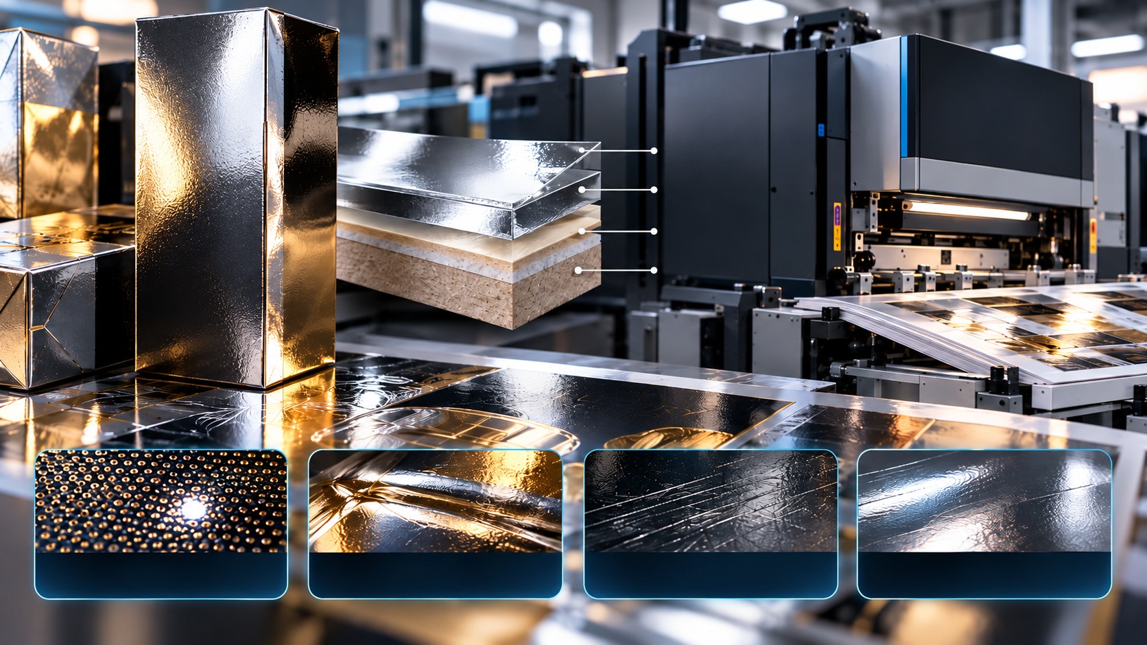
A simplified cross-section of this specific construction, from printed face downward, is shown below. Actual supplier technical data must be checked because other commercial metalized-board constructions reverse the film orientation.
LAYER STACK — FROM PRINTED FACE TO BOARD
Layer/material | Role in this construction |
|---|---|
Optional receptive surface | Print treatment or coating, when qualified |
PET film — printing face | Insulating polymer surface contacted by the LEP print. |
Vacuum-deposited aluminum | Thin metallic reflective layer below the PET |
Cold-lamination adhesive | Bonds the metalized film to the cartonboard |
Cartonboard | Structural folding-carton base |
Other metalized-board grades may use a different orientation; verify the supplier's TDS before setting print or electrical controls.
The laminate introduces several independent interfaces: board to adhesive, adhesive to metalized film, PET surface to printing system, and printed ink to any protective coating. A failure visible in the final carton cannot be attributed to the LEP engine until the relevant interface—and the stage at which damage first appears—has been identified.
The electrical distinction: insulating PET versus exposed aluminum
PET is an electrical dielectric. When PET is the outermost surface, that print face is not made conductive simply because a metal film is buried underneath it. Surface-charge retention and dissipation depend on the actual outer coating, moisture, contamination, contact geometry, and the construction's electrical paths. If an aluminum layer is truly exposed, its surface can be electrically conductive provided the deposited metal is sufficiently continuous. Even then, conductivity of that exposed layer does not automatically establish a usable grounding route through the sheet.
This distinction matters when evaluating static electricity in a sheetfed press. The feeder separates individual sheets, transports them through contact points, and delivers them to a stack. Charge can build or redistribute during separation and friction, affecting sheet behavior, particle attraction, and handling under susceptible conditions. Because the printable PET face is insulating in the construction described here, an aluminum layer embedded beneath it is not a guaranteed path for dissipating surface charge.
The correct response to a suspected electrostatic problem is to confirm the film orientation and surface treatment, measure or otherwise diagnose charging where appropriate, inspect the press-approved static-control arrangements, and follow the substrate and press manufacturer's instructions. Do not assume that a visually metallic face is grounded, and do not modify high-voltage or discharge arrangements outside approved service procedures.
A further distinction is needed for the term "null cycle." Press-published sheetfed production guidance describes a null cycle as an empty separation during which drums rotate without printing. Documented purposes include allowing ink to dry and reducing certain print-quality or mechanical phenomena, including those associated with white-ink printing. That guidance does not establish null cycles as a method for discharging electrostatic charge from a PET sheet. Their use should follow the applicable press model, software, and job instructions—not an unverified static-discharge hypothesis.
Why sheetfed LEP and a metallic surface are a demanding combination
LEP forms an electrostatic image on a photoconductive imaging surface, develops it with electrically charged liquid-ink particles and transfers the image through a heated intermediate blanket before final transfer to the substrate. The image-forming process is therefore distinct from the mechanical route an individual sheet takes through the press. Both can influence the final appearance, but they do not create the same classes of defects.
On a sheetfed press, a laminated board enters through the feeder, is registered and transferred through the press's defined sheet path, reaches the image-transfer region, and then travels to the delivery or stacker. Exact gripper, nip, roller, and support arrangements vary by model. Use the machine's documented transport layout for relevant contact points, not a generic diagram.
The PET surface is smooth and highly reflective. Bright reflected light beneath a thin printable layer makes missing image coverage conspicuous. Mechanical contact can also alter local gloss, even without ink loss. That is why a bright mark on a dark metallic carton describes what an inspector sees—not yet a root-cause diagnosis.
Three similar-looking defects—and three different investigations
A missing ink dot or locally weak printed region may arise from the printing construction: ink condition, substrate preparation, ink transfer, or layer adhesion. Identification requires examination before finishing, at appropriate magnification and viewing angles, and, where applicable, controlled adhesion or robustness tests. The important question is whether an image area never received adequate ink or whether material was removed later.
A nip-pressure mark is different. It may appear as a local change in gloss, a shallow impression, or a subtle topographic disturbance caused by compressive loading at a contact point. The source could be a pressure zone in an upstream laminating machine, a relevant press transport or transfer nip, or a downstream coating or converting machine. Not every nip contact is damaging; what matters is pressure distribution, surface finish, sheet construction, and where the defect first becomes detectable.
A scratch or scuff is different again. Sliding contact with a fixed guide, contaminated roller, gripper-contact surface, sheet-to-sheet abrasion, a hard particle, or a downstream handling point may damage PET or an already printed/coated layer. A long, narrow mark that recurs at a fixed cross-sheet position is a useful clue for a fixed contact location. A periodic mark may implicate a rotating element, but recurrence and mechanical pitch must be measured before making that attribution. These are hypotheses for targeted mechanical inspection, not automatic verdicts.
What UV varnish can conceal—and what it cannot fix
A qualified UV varnish can change the optical appearance of minor surface irregularities. Under some conditions, its leveling and refractive properties may make shallow nip impressions or fine gloss variations less visible. This is an optical masking effect, not proof that the pressure mark or its mechanical cause has disappeared. The result also depends on film thickness, coating formulation, curing, local geometry, and deformation depth.
A genuine scratch is not equivalent to a shallow nip impression. If the PET or ink layer has been cut or displaced, or the metalized layer is damaged, a clear coating cannot reliably reconstruct the original material. A varnish might reduce the visibility of a very superficial line in some constructions, but it must not become the standard correction for an active scraping or scuffing mechanism. Coating over damage without identifying its source simply lets it recur on the next run.
Just as importantly, UV varnish is not universally interchangeable with another protective chemistry. A coating that improves rub resistance or disguises light pressure marks may interfere with hot foil, adhesive bonding, further coating, crease performance, or another downstream finishing requirement. It must be qualified against the finished product. In the source case, the initial protective-varnish experiment involved a water-based coating; the discussion here of UV-varnish masking is an additional engineering consideration, not a claim that UV varnish cured that historical failure.
Trace the sheet, not the symptom.
For recurring scratches or compression marks, the most effective strategy is a controlled defect-location study. Inspect and retain samples of the metalized film before lamination, laminated board before the LEP press, printed sheets at delivery, coated sheets, and cartons after individual finishing stages. Maintain the same sheet orientation and record the defect's position from a reference edge. The purpose is to find the first operation after which a previously clean sheet becomes marked.
If a scratch is present on the unprinted laminated sheet, press image-transfer parameters are irrelevant to its creation. The investigation belongs in film manufacture, storage, or the cold-laminating route. If it first appears between feeder and delivery, the sheetfed press path becomes the inspection boundary: feeder separation and pickup, registration and gripper areas, supported contact points, transfer nips where applicable, and delivery/stacking. If it emerges only after varnishing or die-cutting, the corresponding machine and handling route must be examined instead.
Controlled tests should change one suspected mechanical condition at a time, using the approved safe operating envelope. Inspect contact-surface damage, contamination, burrs, incorrect adjustment, and undue sheet slip. A fix is supported when the defect location and repeatability correlate with the suspected contact and the mark no longer appears following a verified local correction. Do not compensate for a fixed mechanical scratch by indiscriminately increasing primer, ink, blanket settings or protective-coating weight.
The historical LEP failure: clean-looking sheets were not enough
The converter at the center of the case had made its reflective board internally for years. The construction was familiar from conventional printing, and the organization naturally expected it to behave equally well in LEP. The premium cosmetic application, however, still produced small, randomly positioned bright image interruptions and insufficient post-finish robustness. Several earlier interventions had improved selected samples without creating a dependable industrial route.
The visiting application expert began by requesting evidence beyond the stacker: fresh printed sheets, retained samples after time had elapsed, material after coating or conversion, rejected cartons, and examples of finished product that had passed. The comparison established that passing visual inspection immediately after printing did not mean the construction would remain acceptable through the entire route. The finished carton—not the sheet leaving the press—had to define acceptance.
A review of maintenance and process history highlighted the condition of the ink systems, especially white. Some systems had been in service for a long time. Restoring them to an appropriately controlled state markedly reduced missing dots. It was a useful improvement, but a few random reflective interruptions remained, and the customer's acceptance criteria still could not be met consistently.
At that point, continuing to chase a single press parameter would have missed the larger constraint. The expert shifted the question from "how can this image look cleaner at delivery?" to "how can the printed multilayer construction withstand the intended finishing route?"
The protective layer that solved one problem and created another
A trial with a conventional water-based protective varnish substantially improved print robustness. The result provided evidence that post-print protection was an important part of the solution. However, the chosen varnish chemistry interfered with a premium finishing operation required later in the carton's route. The printed surface was stronger, but the package was no longer suitable for all required processing.
That result changed the technical objective. The requirement was not simply to apply a harder or thicker protective layer. It was to introduce a compatible interface that improved resistance to subsequent handling without blocking the finished carton's functionality and appearance.
The unusual solution was to qualify a compatible primer-type chemistry in an unconventional position: above the printed image rather than only beneath it. Applied in a controlled post-print coating operation, the candidate served a protective role while remaining compatible with the downstream finishing requirements in the tested application. This was not a recommendation to use any ordinary preprint primer as an overprint varnish. Chemistry, coat weight, adhesion, drying, appearance, and subsequent finishing compatibility all required qualification.
Material selection and white ink completed the route.
The protective overprint was not, by itself, a universal cure for the original metalized board. When the team compared alternative metalized PET-to-board constructions prepared through the converter's established cold-lamination process, the historical material remained the least robust in the most demanding tests. Other constructions performed better after the same printing, protective coating, and finishing sequence.
The key decision was therefore to select the complete material construction that worked through the end of the process, rather than defend a familiar substrate because it had performed well for years with a different printing technology. Material qualification had to account for the PET printing face, the metallic appearance, interlayer bonding, and the finishing route together.
White-containing image regions remained relatively sensitive. Controlled trials with additional white in the relevant areas produced a further improvement. Double white was retained where the image construction justified it, not added automatically to every job. In sheetfed LEP printing, the print order, ink condition and any drying/null-cycle requirements for such a configuration must follow the qualified press-specific policy.
By the end of the investigation, the production route combined a better-suited metalized PET board construction, controlled ink and surface conditions, a compatible overprint-protective chemistry, additional white where supported by testing, and approval against finished cartons. This was a system-level solution, not a heroic press setting.
Validate the final carton and keep mechanical defects separate
The site repeated the qualified construction through the full workflow and progressively transferred ownership to local production and quality personnel. The evidence had to be consistent across successive runs and across relevant finishing steps. That verification mattered more than any single flawless sheet.
A separate mechanical-defect protocol should accompany such a sensitive sheetfed application. Log and classify bright missing dots, nip impressions, scratches and scuffs independently. Record the earliest process stage at which each appears, and retain both uncoated and coated evidence. Where a varnish appears to hide a shallow mark, verify that the underlying construction and finished product remain acceptable rather than treating the disappearance of its appearance as elimination of the cause.
Electrostatic concerns should likewise be assessed only when the evidence points in that direction. An insulating PET print face and a conductive buried aluminum layer are not contradictory: they are distinct layers with different electrical behavior. No general "null-cycle discharge" recommendation follows from that structure. The right control is whatever substrate conditioning, charge management, and press operating practice is documented, safe, and validated for the actual model and material.
The lesson: the defect is visible at the surface, but the cause may not be there
A metalized carton exposes imperfections mercilessly. Its reflectivity can reveal a missing ink dot, accentuate a shallow compression mark, or make a scratch stand out against otherwise excellent printing. Those observations may look related to an inspector, but they don't share a single root cause.
The lesson of this case is not to reinvent a process that already works. It is to broaden the investigation only when a recurring failure remains unresolved. In the original LEP application, the breakthrough required attention to substrate construction, ink-system condition, post-print protection, white-image design, and finished-carton performance. Where additional scratches or nip marks occur, mechanical contact points require their own targeted diagnosis and correction, not an attempt to hide them with varnish.
Out-of-the-box thinking is not an endless search for unconventional settings. It is the discipline to identify which part of the manufacturing system actually limits the product—and to change only what the evidence shows needs changing.
Source and scope note
The central case is adapted from Chapter 8, "The Week He Should Have Gone Home," in Ronen Dolev's book The Personal Journey of an Industrial Printing Expert (2026). The book explicitly fictionalizes or adapts professional circumstances for confidentiality. The sheetfed-specific transport checklist, PET-versus-aluminum electrical explanation, nip-mark and scratch investigation, and UV-varnish masking discussion are engineering expansions; they are not represented as additional historically documented incidents at that same factory. No numerical working points or substrate-specific approval are implied. Site implementation must follow the applicable material specifications, press instructions, supplier qualifications, and finishing tests.
Technical references
- Ronen Dolev, The Personal Journey of an Industrial Printing Expert (2026), Chapter 8, "The Week He Should Have Gone Home."
- TPL (Technical Plastics Laboratory), Metalized PET Films: board-lamination orientation and printing surfaces.
- Holmen, Metalprint Digital: metalized PET laminated to printing paperboard.
- HP, Liquid Electrophotography digital printing process and intermediate blanket transfer.
- Dong et al., "Preparation and properties of different dielectric films with Al metal electrode," IET Nanodielectrics (2022).