Ronen Dolev | Industrial Printing, Materials, Applications & Color Science
Executive perspective
The color measured on a finished label results from several linked processes, not a single calibration number. In liquid electrophotography, electrically charged pigment/resin particles develop a latent electrostatic image, individual separations build a multicolor ink film on a heated blanket, and that image is transferred to the substrate. In LEPx, those separations originate from several simultaneous imaging engines. This paper examines both the physical formation of color and how a seven-ink CMYKOVG production workflow is calibrated, characterized, and managed on the actual press and substrate. [1, 2, 8–10]
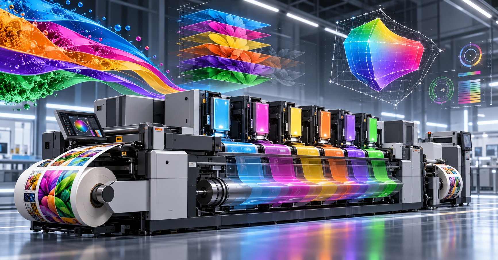
Conventional HP Indigo LEP label architectures typically use one imaging engine to generate separations sequentially. HP Indigo LEPx, represented here by the V12, uses six simultaneously active imaging engines, each with LED writing, a Photo Imaging Drum (PID), and the ability to select from two Binary Ink Developers (BIDs). Separations are imaged in parallel yet assembled successively on a moving blanket belt. The complete composite image is subsequently delivered to the substrate in a single final transfer. This distinction between parallel imaging and sequential assembly is the central engineering premise. [1–3]
A central qualification is needed. LEPx certainly involves color calibration and color matching; the manufacturer publicly promotes automated color systems for the V12. But the availability and scope of particular automated spot-color, inline-measurement, or closed-loop functions can depend on press configuration, software release, and installed workflow. Consequently, this article distinguishes well-established color-engineering requirements from verified product capabilities, and makes no universal claim for a named feature without a public, model-specific basis. [2, 10]
1. Define the boundary: process physics and production color management
Image quality has at least three layers of causation: data preparation (rasterization, separation and halftoning), physical image formation (charging, exposure and development), and formation/transfer of the final ink film. A color-management correction acts primarily on the demanded image values. It cannot independently determine whether an unexpected band, edge shift, or local density deviation began at the photoconductor, the developer, the intermediate transfer surface, or the substrate interface.
The preceding papers examined architecture and compared it with conventional printing and label materials. This fourth study adds a distinct missing link: how LEPx translates physically developed CMYK and OVG separations into a controlled, characterized extended-gamut output on a specified substrate, without treating color matching as merely a RIP property.
2. Electrical image formation: a charge pattern before a color patch
In liquid electrophotography, a charge unit establishes the initial electrical condition of the photoconductive surface. Optical exposure selectively alters the surface potential to define a latent electrostatic image. Development converts this electrical pattern into a visible image through charged pigment/resin particles in liquid carrier. The electric field, particle charge, and local material conditions jointly govern that development; it is not merely a case of placing a CMYK value onto a mechanical plate. [1, 4, 5]
For the V12, HP's public 2020 white paper describes a PID whose image areas are exposed by an LED cluster, then developed using a BID. That same published source describes conventional LEP as using a laser-scanning writer and a PIP (Photo Imaging Plate). Both architectures use electrostatic latent-image formation, but the writing geometry and photoconductor implementation change. [1]
What a process engineer should infer-and should not infer
An image may be altered by any mechanism that changes the relationship between exposure, latent charge, and liquid-ink deposition. Spatially varying exposure, different electrophotographic response, and variation in development may appear as density or edge differences after transfer. These are general, testable electrophotographic mechanisms. They do not establish that the V12 actually suffers from them, nor do they reveal the V12's proprietary compensation methods.
A useful publication-level distinction is between a mechanism that could produce a deviation and an observed deviation proven to have that mechanism as its root cause. Without controlled observations, the former must never be presented as the latter.
3. Laser-scanned PIP versus array-written PID
A scanned laser and a fixed LED writing array both deliver spatially controlled light, but distribute the writing task differently. The former forms lines through optical scanning; the latter uses a large array of optical emitters. The publicly published LEPx design is described as using thousands of LEDs per writing head and a photoconductive drum at each engine. [1–3]
This difference changes the exposure-system architecture. Image-addressability should nevertheless be distinguished from raster-data resolution and effective print detail. HP currently publishes 1,624 dpi image addressability and 812 dpi RIP resolution for the V12, while listing halftone screen options of 175, 196 and 200 lpi. These are distinct process descriptors and cannot be used as interchangeable measures of dot definition. [2]
At the print level, compare positive and negative fine lines, highlight continuity, image-edge variation and spatial uniformity. These tests matter because they interrogate the written/developed feature after transfer. A higher nominal addressability would not, by itself, prove reduced dot irregularity, superior tone reproduction or better inter-separation registration.
Why independent engines alter the diagnostic question
In a single-engine LEP configuration, several separations are created through the same central writing/development path at different times. In LEPx, multiple engine paths create separate image components concurrently. This changes how one should structure a comparison: first characterize the output of each separation, then compare the consistency of the assembled image. An observed fault confined to one separation and a fault shared by all separations require different hypotheses. That is an analytical framework, not a statement about any internal HP fault-detection implementation.
4. BID development: controlled liquid-ink deposition is still fundamental
The Binary Ink Developer (BID) carries a controlled film of liquid electrophotographic ink and participates in selective development of the latent charge image. The developer does not determine the final color solely from a nominal colorant formula; development behavior depends on the system's electrical and fluid properties. Tzori's peer-reviewed conference paper, describing earlier Indigo generations, identifies ink concentration, conductivity, flow, temperature, and photoconductor charging/discharging as relevant process-control quantities. Its historical scope must be explicit: it neither measures the V12 nor proves that the later machine shares any particular control algorithm. [4]
The publicly documented V12 configuration associates two selectable BIDs with each of six imaging engines. This provides twelve on-press ink positions, but only one chosen separation per engine in a given imaging cycle. Thus, twelve installed inks do not mean twelve color images are developed concurrently. [1–3]
What "same ink family" does and does not establish
HP identifies both architectures as using its proprietary HP Indigo ElectroInk family. LEP is the generic process term; ElectroInk remains a commercial designation. Ink-family continuity is evidence that LEPx is not based on an unrelated fundamental printing chemistry. It is not proof that every colorant, ink formulation, physical setting, or deposited film property is identical across specific presses and jobs. [1]
For a public experiment, compare one-color prints from documented, approved ink configurations. The measurement should be designed to establish output behavior-solid-field uniformity, tone reproduction, fine-feature integrity-not reverse-engineer or disclose unpublished settings.
5. From parallel creation to sequential blanket-belt accumulation
The most consequential distinction in sequence is often missed. Six engines may form latent and developed images at the same time, while a segment of the heated blanket belt encounters the engines at successive positions. Each engine deposits its developed separation onto the moving intermediate transfer surface. The individual color components therefore accumulate sequentially on the belt before the composite film is transferred to the web. HP's openly available diagram and stepwise narrative describe this conceptual flow precisely. [1]
Consequently, "parallel color printing" does not imply that six separate color films arrive at the substrate through six printing nips. The substrate receives the assembled image from the blanket. Conversely, "one-shot" describes the final multicolor transfer; it does not mean all colorants were created or laid onto the blanket in a single physical event.
PROCESS FLOW - conceptual, independently typeset from publicly documented principles (not an HP schematic):
SEPARATE IMAGING PATHS | SHARED ASSEMBLY / FINAL TRANSFER |
|---|---|
Engine 1: charge → LED expose → BID develop | First selected separation enters blanket belt |
Engines 2–6: concurrent charge/expose/develop | Further separations join that same belt image in sequence. |
Optional subsequent imaging cycle for >6 separations | Composite film reaches the substrate-transfer nip |
Output measurement and physical product evaluation | One-shot delivery of the complete image to the web |
A blanket belt changes the geometry of intermediate transfer relative to a drum-mounted blanket. It invites questions about registration timing, belt movement, contact history, and assembled-film response. Neither belt length nor parallel imaging specifies the temperature history, deposited mass, film thickness, or adhesion performance of a particular job. Those outcomes require independent evidence.
6. Layer sequence, transfer and the meaning of the final image stack
Once a developed separation moves from the photoconductor to the heated blanket, the resin-bearing ink particles form a cohesive, transferable image film. Subsequent separations build onto that film. The public LEPx process description explicitly links the heated blanket to consolidation of the resin-rich image and the eventual one-shot transfer to the substrate. [1, 6]
The sequence is especially relevant for jobs with opaque white, specialty colorants, or repeated separations. The manufacturing engineer should differentiate three things: ink station availability; the order in which separations assemble on the intermediate surface; and the physical/optical order of layers after final transfer. Confusing these levels can lead to misleading interpretations of white opacity, reverse printing, and mixed-color appearance.
It would be unjustified to claim that the LEPx blanket belt always forms a thinner, glossier, or more strongly adhered image than a conventional LEP blanket. Even if layer order and cycle count differ, you must establish the end result on matched substrates using documented job conditions. Film thickness, opacity, surface appearance, and adhesion are independent response variables-not guaranteed benefits of more imaging engines.
7. Registration now has two distinct coordinate problems
Image registration in LEPx should be understood in two coordinate systems. First, inter-separation registration must be achieved on the moving intermediate belt, where individual imaging engines contribute their color images. Second, the already assembled image must be correctly positioned and dimensioned relative to the moving substrate. These are different sources of geometric error and must not be collapsed into a single "registration" number.
This distinction is why comparing LEPx directly with serial flexographic color stations can be misleading. Conventional multi-station flexography repeatedly transfers separate colors to a moving web. LEPx requires coordinating multiple image generators upstream of the shared one-shot transfer, rather than transferring each color separately to the web. [1, 3]
For an independent experiment, measure displacement among color separations using registration targets at multiple positions across and along the printed web. Independently measure repeat length, overall image scale, and image-to-web position. Machine Direction (MD) and Cross Direction (CD) should be reported separately. A visually acceptable single sample is insufficient evidence of long-run geometric stability.
8. Six separations, two cycles and twelve installed inks
HP documents a V12 production mode with up to six separations at up to 120 m/min and a seven-to-twelve-separation mode at up to 60 m/min. The published architecture links the second case to an additional belt cycle. This is a physical scheduling constraint-not simply a change of a color-profile setting. [1–3]
A six-separation job is not necessarily equivalent to a CMYK job, and a CMYKOVG job that truly uses all seven colorants crosses the six-engine limit for a single belt cycle. Repeated white layers, specialty channels, and true spot inks each consume physical separation opportunities. The production schedule must be derived from the actual output channels, rather than the number of visually distinct hues or the number of installed ink containers. [1–3, 8–10]
An evidence-based LEP–LEPx comparison should therefore record the number of physical image separations, screen selection, actual output sequence and operating mode. It should not infer that two-cycle images necessarily have different optical density, trapping, color fidelity or durability. These are hypotheses to test, not established consequences of the extra cycle.
9. CMYKOVG is a physical seven-color process, not a CMYK software preset
What Orange, Violet and Green actually contribute
The published V12 ink portfolio includes Cyan, Magenta, Yellow, Black, Orange, Violet, Green and Premium White. Orange, Violet and Green (OVG, also encountered as OGV when listed in another order) are real colorant channels, not abstract extensions of a CMYK color profile. In extended-gamut printing, these inks create additional colorant combinations that may reproduce some saturated hues and spot-color targets more accurately than a given CMYK configuration. HP and Pantone both describe this seven-color principle publicly. [2, 8, 9]
OVG is not that every pixel must contain seven inks. A correctly constructed multi-channel separation uses additional channels selectively where they improve colorimetric reproduction, gradient behavior, or practical spot-color coverage. A neutral tone, a dark image region, and a highly saturated orange may require very different colorant combinations. Their actual separations depend on the output characterization and color-conversion strategy, not on a universal recipe.
Neither seven installed inks nor a chart labeled "extended gamut" demonstrates the size of the achievable gamut on a specific paper or film. Substrate white, opacity, ink behavior, halftoning, permissible overlap, and measurement conditions constrain the realizable color volume. The advantage is conditional and measurable, not automatic.
Why six engines matter to a seven-color job
The V12 architecture comprises six concurrent imaging engines, each with two selectable BID sources, while the press offers up to twelve ink stations. Only six color separations can be imaged concurrently in one belt cycle. A job that physically uses CMYK plus Orange, Violet and Green requires seven separations and therefore belongs to the published additional-cycle production class, rather than the up-to-six-separation class. The manufacturer specifies up to 120 m/min for up to six separations and up to 60 m/min for seven to twelve. Those are maximum stated press modes, not guaranteed net throughput. [1–3, 10]
This creates an unusual but fundamental design decision: the color-management system can aim for a wider gamut with seven printed channels, but manufacturing must also assess whether the extra physical separation, second blanket cycle, and throughput consequences add value for the job. The correct comparison is an accepted-color yield and production cost at a defined customer target, not simply CMYK versus CMYKOVG in isolation.
Do not confuse process-color expansion and a genuine spot ink.
An extended-gamut simulation of a PANTONE or other brand color combines process inks. A dedicated spot ink is a separately formulated colorant occupying its own print station. These alternatives can differ in spectral properties, achievable color, number of printed separations, and operating economics. Manufacturer claims about coverage of a large percentage of a spot-color library must always be tied to the specific set of inks and matching method stated; they must not be read as a universal guarantee that CMYKOVG alone reproduces every spot color on every substrate. [1, 2, 8, 9]
10. Gamut expansion begins with a characterized seven-channel print condition
A seven-color gamut is the measurable output domain of a defined physical print condition: a particular press, active ink set, paper or film, primer where needed, screening mode, calibrated solids, tonal responses and overprint behavior. A press is not automatically "in seven-color gamut" merely because Orange, Violet and Green cans are installed.
The characterization must sample relevant one-, two-, and multi-channel combinations and establish a reproducible relationship between requested colors and attainable output values. The resulting model can support separation optimization, spot-color emulation and prediction of out-of-gamut behavior. A CMYK-only ICC description should not simply be relabeled CMYKOVG: conversion to seven output channels requires a properly supported multi-channel model and compatible DFE/workflow configuration. [8, 11, 12]
Output conditions and screening cannot be ignored.
HP publishes V12 halftone choices around 175, 196 and 200 lines per inch, with defined image addressability and RIP resolution. A gamut characterization built under one halftone or substrate condition may not remain quantitatively valid under another. Likewise, changing the ink set, primer, substrate white, or production mode can invalidate the assumptions of an earlier fingerprint. [2, 10]
For a fair LEP-versus-LEPx experiment, first compare matched physical ink sets and substrates wherever technically feasible. Then separately compare the best available and properly qualified gamut configuration of each platform. Otherwise, a benefit from adding OVG could be misreported as a benefit inherent to LED writing or blanket-belt architecture.
Where OVG can help and where it cannot
OVG may reduce color difference for selected saturated brand hues outside a particular CMYK gamut. It may also create new options for separation design. Yet an ink cannot create a color that the substrate's reflectance and the available spectral colorants cannot support. Profile mapping also can't fix a physically unstable ink layer, mottle, weak adhesion, or poor registration. Gamut expansion and process stability must be qualified independently.
Question | CMYK-only configuration | CMYKOVG configuration |
|---|---|---|
Active process channels | Four process colors. | Seven distinct physical inks if all CMYKOVG separations are printed. |
V12 imaging-cycle class | Within six-separation one-cycle class. | Printing all seven channels places the job in the additional-cycle class. |
Gamut expectation | Limited by CMYK ink/substrate response. | Potentially enlarged for certain saturated hues, subject to measured characterization. |
Required characterization | A defined four-channel print condition. | An explicitly supported multi-channel print condition, including O/V/G behavior. |
Spot-color reproduction | CMYK emulation or separately printed true spot. | Seven-channel emulation where supported, or separately printed true spot. |
Principal trade-off | Simpler separation and faster maximum press mode. | Potentially broader color coverage, more channels to control and a possible throughput cost. |
11. Color calibration on LEPx: bring the seven channels to a controlled state
Yes, LEPx presses require color calibration and color matching. The printed result cannot be expected to remain stable solely because the image is written digitally. Optical exposure, charged-particle development, ink condition, transfer behavior, and the substrate collectively affect each channel. The V12 product literature expressly promotes automated color systems, but that does not mean every individual calibration module offered elsewhere in the HP Indigo family is present, enabled, and identical in every V12 software release. [1, 2, 10]
Three levels of correction have different jobs.
First, physical press-process adjustment aims to keep each imaging/development path within its qualified operating state; exact internal algorithms and service settings are outside the scope of a public article. Second, printing calibration aligns the measured tone and color response of the active process channels to a chosen, repeatable press condition, on the applicable substrate. Third, color characterization and DFE conversion connect that condition to the desired customer or industry printing aim. Changing an ICC profile to compensate for a physical defect reverses this logic and may conceal the cause.
A seven-color production condition adds three channels to the calibration and control problem: Orange, Violet and Green each require measurement and control appropriate to their role. Monitoring only the four CMYK solids cannot establish that a seven-color reproduction is stable. Conversely, seven-channel calibration does not necessarily mean seven separate unrelated calibration tools: the workflow may coordinate measurements and transformations using software and instruments supported in the installed configuration.
The production sequence that makes engineering sense
Before a critical job, identify the actual substrate and ink configuration. Bring the print engine into its manufacturer-qualified operating condition. Print and measure a stable reference target that contains the installed and intended active channels, their relevant tone scales and selected overprints. Recalibrate according to the applicable approved procedure where results exceed the defined control limits. Only when the press reproduces its characterization condition should the DFE convert the job toward customer targets. Retain a measured quality sample and monitor the run at a frequency appropriate to the required tolerances.
This is a general, reproducible color-engineering sequence, not a claim about the names of particular V12 wizard screens, automatic feedback mechanisms, or unpublished electrical adjustments. Commercial integration of inline scanners and measurement modules must be checked for the actual product and software release.
Screen-dependent and substrate-dependent calibration
Associate a media fingerprint, LUT, or output profile with the physical substrate and screening mode for which it was measured. Coated paper, uncoated paper, opaque BOPP, transparent film printed over white, and a metallic surface do not necessarily produce the same tone or color response. For paper containing optical brighteners, record the measurement mode and backing. An operational calibration that restores a reference aim cannot by itself expand the physical color gamut. [11, 12]
Process layer | What it controls | What it cannot prove |
|---|---|---|
Engine/development control | Repeatability of written and developed color separations. | That an ICC match or spot-color appearance is correct. |
Output calibration | Return of relevant active channels and tone behavior to a reference state. | That OVG is automatically used or that the gamut has grown. |
Multi-channel fingerprint | Measured response of specific substrate, inks, screening and overprints. | That the same profile is valid for all media or press versions. |
DFE / color conversion | Conversion of input intent into supported output separations. | That ink transfer, surface adhesion, or engine uniformity is physically sound. |
Production validation | Actual target conformity, stability, and run-to-run agreement. | The internal cause of a deviation without targeted diagnosis. |
12. The DFE connects color intent with six imaging engines and seven inks
The Digital Front End performs more than ordinary four-color rasterization. In a qualified extended-gamut workflow, it must interpret input colors, process or preserve spot-color definitions as intended, convert colors to the supported output channels, select the appropriate screening and trapping behavior, and supply separations that the press can physically schedule. The V12 lists HP PrintOS Production Pro for Labels and Packaging as its print server. [2, 10]
It is useful to picture four connected stages: customer artwork and spot definitions; source/destination color transforms; construction of a particular ink-channel separation set; and physical imaging of the chosen separations on the LEPx engines. The last stage has the six-engine / blanket-cycle constraint. An ICC or color-server decision to invoke Green, for example, is consequential only when the output file and actual press configuration preserve and print a Green separation.
CMYK data and spot names are not equivalent inputs
A process-image object containing CMYK percentages, an RGB image, and a named spot-color object can follow different conversion paths. In a press-ready job, spot colors must have a clear treatment: preserve as a qualified true spot where available, emulate through CMYK, or emulate through an approved extended-gamut ink set. The resulting color and separation count can differ materially. A generic statement that a DFE "supports PANTONE" does not specify which of these routes is used.
Why a seven-channel workflow needs explicit mapping
Seven-channel separations require decisions about channel usage, total printed colorant, overlapping separations, neutrals, highlights, and gradients. Various prepress systems implement those decisions differently. A transform should therefore be validated for visible artifacts and for whether the resulting active channels are physically supported by the selected V12 configuration. The system should not silently treat a seven-channel job as a normal six-separation production mode.
Do not generalize workflow-feature names.
Generic HP Indigo literature describes built-in spectrophotometry, continuous calibration, fingerprint sharing and named color-automation offerings. The public V12 brochure and product page establish the V12's color automation proposition, but the availability of specific spot-color automation, trapping functions, scanner-driven feedback, or closed-loop corrections is not universal across all models and releases. A public technical article must make that distinction instead of treating every Indigo-family tool as a confirmed V12 capability. [1, 2, 10]
13. Practical decisions: spot targets, seven-color gamut and throughput
Consider a label containing a saturated orange brand element, photographic imagery, small reverse text and an opaque-white underlayer on transparent film. The content alone does not determine the best process configuration. The engineering decision begins with a color target, acceptable tolerance, physical substrate construction, and the required net production volume.
One qualified solution may emulate the brand color using CMYK, preserving a simpler active-channel set and the press's higher stated speed class. Another solution may invoke the Orange channel, or all CMYKOVG channels for the entire artwork if the characterization supports the desired result. A third may use a true spot ink. White adds another physical separation and can change how many cycles the selected color construction needs. Evaluate these alternatives by printed color accuracy, finish performance, and total job efficiency, not by gamut volume alone.
A color approval workflow for LEPx
A robust acceptance sequence is: specify a measurable reference (including viewing and measurement conditions); identify the ink/white/substrate construction; select the lowest-complexity qualified separation method able to meet the target; establish calibration and multi-channel fingerprint validity; print an accurate proof at representative production settings; inspect brand patches and full-image transitions; and confirm both a pass/fail target and within-run stability. For cross-press migration from conventional LEP, repeat the acceptance checks rather than transferring unqualified LUTs or profiles.
If OVG is not needed for the job, its availability alone offers no color-quality benefit. Where OVG is necessary and qualified, it may justify an extra production cycle. The economic outcome is job-specific, particularly when a seventh channel is active or when many SKU changes are required.
Failure localization when the color is wrong
If a single solid Orange patch drifts, first investigate evidence specific to that channel under an approved production workflow. If CMYK solids remain within targets but mixed brand colors drift, examine overprint interaction and the validity of the extended-gamut transformation. If registration defects appear at colored edges, investigate inter-separation and image-to-web geometry. If the entire print shifts after switching substrates, inspect substrate condition, primer suitability, and the fingerprint the DFE chose. Final ΔE alone is insufficient to distinguish these causes.
14. Spatial image behavior: when a final color difference conceals its origin
A final color patch results from writing, development, layer assembly, and substrate transfer. Two patches may have a similar average spectrophotometric result while one shows more spatial variation or irregular printed edges. Conversely, a visually even solid may sit slightly away from a specified colorimetric aim. These outcomes should be treated as different response categories.
For process diagnosis, compare: uniformity across the web (CD); variation along the web (MD); edge sharpness and continuity at the same nominal screen; single-color response before assessing multicolor overprints; and response stability at representative production speed. This is an analytical recommendation informed by known electrophotographic mechanisms, not a report of an unpublished V12 problem.
The physical distinction between spatial uniformity and average color is critical. A single ΔE number cannot resolve whether a localized shift is caused by the writing path, development, transfer, or substrate. Only a deliberately structured test can narrow the causal possibilities.
15. Why the DFE cannot be treated as an interchangeable part of the press physics
RIP, halftoning, trapping and separation planning determine the digital instructions sent to the image-forming system. The physics of charge development and intermediate transfer determines how these instructions become a printed film. Comparing two presses with an unmatched screen or color-separation strategy confounds software-driven differences with imaging-architecture differences.
Publication-level comparisons face another limitation: advertised DFE capabilities, specialty-color functions, and the degree of automation can vary by product generation, configuration, and software release. A statement about one software version should not be universalized to all V12 installations or to the LEPx physics itself. Because the article is intended for an unrestricted audience, no customer-only release notes, service documentation, or version-specific internal support material are used as sources for such claims.
Calibration LUTs, substrate characterization and ICC-based conversions are not optional background concepts in LEPx. They are essential to controlling output from several independent imaging engines and, when required, Orange, Violet and Green channels. We therefore focus here on the role and sequence of those operations rather than repeating generic color-science tutorials. Do not present a generic HP Indigo feature as a guaranteed V12 feature unless its implementation is verified for the applicable version. [1, 2, 10–12]
Extended-gamut process behavior requires separating the stability of the seven physical ink channels from the response of their multi-channel combinations. CMYK solid targets alone cannot qualify a CMYKOVG condition; the printed target must also include O/V/G solids, tone steps and representative combined colors. For V12 in particular, record whether the job uses at most six active separations or a seven-to-twelve-separation production mode. These facts belong in the research record alongside screen selection and substrate.
16. A process-focused comparison protocol
A meaningful external study should compare conventional LEP and LEPx in the same nominal web-width class using substrates qualified for both. It must declare whether it is testing the physical imaging architecture, CMYK equivalence, or the maximum qualified CMYKOVG gamut of each system. These are distinct experiments. A seven-color configuration cannot be compared to four-color CMYK and the difference attributed only to the blanket belt or LED writing.
The design below avoids unpublished press settings. It relies on printed targets, recorded job conditions and standard laboratory observations that could, in principle, be reproduced by an independent research team.
TEST BLOCK | RESPONSE VARIABLES | INTERPRETIVE QUESTION |
|---|---|---|
Single separations | Spatial uniformity, edge continuity, representative tone patches | Does any difference arise before multicolor assembly? |
Registered two-color targets | MD/CD displacement distributions, repeat-to-repeat changes | Is the visible error inter-separation or image-to-web? |
Four-, six- and >six-separation jobs | Production-mode record, image geometry, localized uniformity | Does complexity or the second cycle change measurable output? |
White + process-color construction | Defined optical opacity, layer-appearance and coverage metrics | Is appearance explained by layer design rather than "LEPx" alone? |
Time-series sampling | Beginning/middle/end and run-to-run distributions | Does the output remain reproducible at production conditions? |
Finished-product check | Film appearance and application-specific acceptance | Does press quality translate into usable labels? |
Sampling and interpretation
Use at least three sampling positions across the usable image width and predefined longitudinal intervals. Sample each technology at its declared, quality-acceptable production speed-not necessarily the highest brochure speed. Record substrate identity and conditioning, screened job information, installed ink set, and any process preparation such as priming. Repeat when practical to distinguish within-run variability from day-to-day repeatability.
Avoid declaring "architectural superiority" from a single run. A credible result needs a variance estimate, a transparent acceptance criterion, and independent repeat measurements. Where ink or material configurations cannot be matched, disclose the mismatch and limit the causal claims accordingly.
17. Evidence boundary: what can be stated and what remains open
PUBLICLY DOCUMENTED | REQUIRES A COMPARATIVE EXPERIMENT |
|---|---|
LEPx uses six imaging engines, LED writing, PID, and selectable BID sources [1–3]. | Whether a given V12 print is more spatially uniform than a comparable LEP print. |
Separations are imaged in parallel and assembled successively on a shared belt [1]. | Whether blanket-belt architecture changes ink-film thickness or optical scatter. |
The composite image reaches the substrate in one-shot transfer [1, 6]. | Whether registration or substrate distortion is consistently lower in a given application. |
Published V12 operating modes depend on separation count [1–3]. | Whether two-cycle work produces a physically different or less stable layer stack. |
Earlier LEP research links charge/ink control to print response [4]. | Which current V12 control strategy governs any observed output phenomenon. |
This boundary matters for readers outside the manufacturer, including competitors. A technically sound article can openly discuss patents, product descriptions, and journal publications. It should not present confidential maintenance updates or customer-specific engineering notes as public research evidence.
Conclusions - the architecture changes the color-making process, not the laws of color
LEPx advances liquid electrophotography by distributing image formation across six simultaneous engines while preserving charged-particle development and indirect thermal transfer. Compared with the sequential LEP imaging path, LED writing, PID surfaces, selectable BID sources and blanket-belt assembly change how separations are created and registered. The same press also supports genuine Orange, Violet and Green colorants, enabling extended-gamut output when the ink set, print mode and DFE transformation are properly qualified.
Parallelism does not mean that all the colorants are laid down on the blanket simultaneously. Separations form concurrently at the engines but assemble successively along a shared belt; the composite image transfers to the substrate in one shot. The same architecture can produce a conventional CMYK image or a wider-gamut image using real OVG inks. Seven physical CMYKOVG separations additionally cross the six-engine-per-cycle limit. These are manufacturing facts, not merely color-profile choices.
Public V12 specifications establish the availability of CMYK, OVG and Premium White inks, the six-engine/twelve-station architecture and the stated color automation proposition. These facts do not establish that every installation runs every automated calibration tool, that seven-channel color is always beneficial, or that a CMYKOVG job has the maximum six-separation speed. Actual color output must be characterized and validated on the substrate. [1, 2, 8–10]
The useful question for future printing research is not whether LEPx can be calibrated—it can and must be. It is how stable charge development, the seven possible process-color channels, physical imaging-cycle scheduling, a validated multi-channel output profile, and calibration discipline combine to produce a repeatable, accepted print. That is a process-engineering question, not a generic ICC tutorial.
Public technical references
[1] HP Indigo. The HP Indigo LEP / LEPx Technology & The Future of Digital Printing. White paper, March 2020. See pp. 14–16, especially, for the documented architectural comparison and the LEPx seven-step process. https://www.hp.com/content/dam/hpi/press/press-kits/2020/pre-drupa-hp-portfolio-reveal/HP_IND_A4_LEPx_whitepaper.pdf
[2] HP. HP Indigo V12 Digital Press. Official published technical specifications for image resolution, RIP resolution, screen options, available inks, and published operating speeds. https://www.hp.com/us-en/industrial-printers/indigo-digital-presses/labels-flexible-packaging-digital-presses/v12-printing-press.html
[3] Labels & Labeling. HP Indigo Demonstrates V12 Digital Press. Independent trade-press account, 20 May 2022, describing simultaneous image generation and belt assembly. https://www.labelsandlabeling.com/labels/features/digital-printing/hp-indigo-demonstrates-v12-digital-press
[4] Tzori, G. Control Mechanisms for Print Quality Assurance in HP Indigo Presses. Proceedings of NIP20, Society for Imaging Science and Technology, 2004, pp. 586–593. Describes earlier-generation LEP control principles; not a V12 study. DOI: 10.2352/ISSN.2169-4451.2004.20.1.art00015_2. https://library.imaging.org/print4fab/articles/20/1/art00015_2
[5] Li, K., Karunanayake, D., Hasegawa, T. and Hoshino, Y. Review of Toner-Based Printing Technologies and Fundamentals of Toner Charging Mechanism. Journal of Imaging Science and Technology 54(5), 2010. General electrophotographic physics; not a LEPx performance trial. https://library.imaging.org/jist/articles/54/5/art00002
[6] HP. HP Indigo LEP Digital Printing Technology. Public explanation of indirect heated-blanket image formation and direct-contact transfer. https://www.hp.com/gb-en/industrial-printers/indigo-digital-presses/lep-digital-printing-technology.html
[7] HP. HP Indigo V12 product brochure, public edition 4AA7-7062ENW. Describes LED/PID/BID engines and a blanket-belt image assembly path. https://digitalprinting.hp.com/content/dam/sites/possibility-city/indigo-printers/v12/pdp/4AA7-7062ENW.pdf
[8] Pantone. PANTONE Extended Gamut Color Printing. Explanation of adding Orange, Green, and Violet to CMYK and the role of XG spot-color simulation. https://global.pantone.com/customer-service/help/?t=pantone%C2%AE-extended-gamut-color-printing
[9] HP Indigo. There's Life Beyond CMYK: Orange, Violet and Green. Public HP Indigo extended-gamut publication. https://digitalprinting.hp.com/content/dam/sites/possibility-city/indigo-printers/growth-and-value-creation/C12.20%20The%20Colour%20of%20Success.pdf
[10] HP Indigo. HP Indigo V12 Digital Press, public brochure 4AA8-2066ENW, March 2026. Confirms supported CMYK/OVG/white portfolio, Production Pro print server, speed, image modes, and public color-consistency proposition. https://h20195.www2.hp.com/v2/getpdf.aspx/4AA8-2066ENW.pdf
[11] Esko. Color Pilot User Guide, version 24.11. General public documentation on measurement, ink characterization, and digital-print spectral workflows. This is not proof that any particular Esko Color Pilot module is enabled on a V12 installation. https://docs.esko.com/docs/en-us/colorpilot/24.11/userguide/pdf/ColorPilot.pdf
[12] MeasureColor. HP Indigo Calibration. Public example of characterization, color-managed conversion and correction LUTs; workflow-specific and not a universal V12 implementation. https://measurecolor.com/features/hp-indigo-calibration/
Publication and intellectual-property note
This independent engineering review is intended for unrestricted public distribution and references publicly available product specifications, published science, and third-party technical resources. HP Indigo, LEPx, and HP Indigo ElectroInk identify particular commercial technologies and trademarks; PANTONE names refer to their owners' color systems. Claims about press modes and supported ink families are manufacturer-reported and can vary by configuration. No confidential engineering service procedures, customer-only software release notes, proprietary electrical settings, ink formulations, unpublished algorithms, or internal quality results are used as publication evidence. No head-to-head physical trial was performed; proposed comparisons and anticipated benefits are explicitly conditional on validation.