By Ronen Dolev | 2026
What Is Blister Packaging?
Blister packaging is a familiar format for presenting and protecting small consumer products. It typically combines a printed paperboard card, known as a blister card, with a preformed transparent plastic cavity. The plastic holds the product in place and makes it visible, while the card carries branding, instructions, product information, barcodes, and any applicable warnings.
The principal advantage is that the product and the printed message remain visible together. For manufacturers and converters, the construction can also provide a practical balance of display value, mechanical protection, pack security, and production cost, provided that its materials and sealing system are suitable for the intended use.
Blister packs exist in several forms, including face-seal cards, trapped blisters, hinged clamshells, and paperboard-based alternatives. This article focuses on the face-seal blister, where the flange around a thermoformed plastic cavity is heat-sealed to a specially coated, printed paperboard card. The finished pack is not simply a printed sheet and a piece of plastic: it is a functional assembly whose materials, interfaces, and thermal history must work together.
Which Products Are Suitable for This Application?
Face-seal blister packaging is particularly appropriate for small goods that benefit from visible presentation, controlled retention, and sufficient card area for graphics and information. Typical examples include electronics accessories such as memory devices, adapters and cables; small hardware such as screws, hooks and fasteners; lightweight hand tools and replacement parts; stationery and office accessories; arts-and-crafts items; toys and game accessories; and selected personal-care or cosmetic accessories.
The application is particularly useful when a buyer needs to see the actual product rather than rely on a printed photograph. Digitally printed cards also make it easier to manage short or medium production runs, multiple languages, regional variants, changing graphics, and variable information without the setup associated with conventional printing plates.
However, suitability cannot be decided from appearance alone. Product weight and geometry, required opening force, resistance to tampering, shelf-life expectations, recyclability, and protection against moisture or contamination all affect the decision. The case discussed here concerns consumer-goods face-seal blister packaging. It is not an approval route for pharmaceutical, sterile, or hermetically sealed packs, for which barrier, regulatory, and integrity requirements may rule out an intentional venting opening.
The Construction: What Actually Bonds to What?
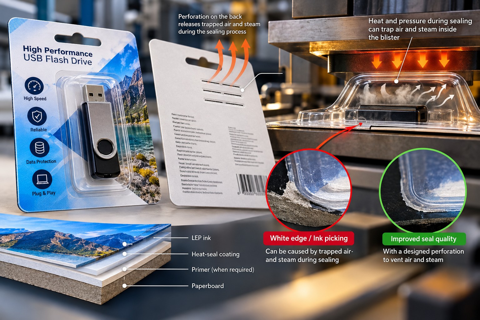
Understanding the layers is essential before discussing any failure. In the relevant sealing area, the construction can be described from the card outward as paperboard; a primer where required; a printed LEP ink layer where the artwork covers that area; a functional heat-seal coating; and the flange of the thermoformed plastic cavity. The exact presence of ink beneath the sealing flange and the coating arrangement depend on the approved artwork and construction.
Layer or component | Primary function |
|---|---|
Paperboard | Mechanical support, stiffness, die-cutting performance, and controlled fiber-tear behavior |
Primer, if required | Preparation of the paperboard surface for reliable LEP ink transfer and anchorage |
LEP ink | Printed branding and information, with image coverage depending on the artwork |
Functional heat-seal coating | Heat-activated bonding interface between the card and plastic flange |
Thermoformed plastic flange | Contact area through which the plastic cavity is attached to the coated card |
The plastic cavity may be manufactured from PET, PVC, or another material qualified with the chosen sealing coating. The card itself is commonly a packaging-grade paperboard selected not only for print quality but also for fiber structure, thickness, grain direction, cutting properties, and the required opening behavior.
An important distinction is often overlooked: a functional blister heat-seal coating and a heat-resistant protective overprint varnish are not automatically the same thing. The first enables the bond to the plastic. The second, when required, protects the printed surface from heat, sticking, scuffing, or distortion, depending on which side is exposed to the heated tooling. Some qualified coating systems can satisfy more than one requirement, but that must be demonstrated rather than assumed.
Why Use Sheetfed LEP for Blister Cards?
Liquid Electrophotography (LEP) is a digital printing technology in which electrically charged ink particles take part in forming the image. In the appropriate process configuration, color separations are assembled on an intermediate transfer surface and subsequently transferred to the substrate. For blister-card production the card stock passes through a sheetfed digital printing press as individual sheets, not as a continuous web.
This provides a practical route to fine detail, consistent registration, short runs, localized artwork, and variable designs. Where the application requires it, the paperboard must first receive a suitable primer. After printing, the surface may require a qualified treatment before coating to obtain sufficient wettability and coating adhesion. Excessive treatment is not automatically better; it can introduce its own durability risks.
The complete manufacturing sequence includes selecting and conditioning the board, preparing artwork and any functional perforation geometry, priming where required, printing on the sheetfed LEP press, applying and drying the sealing coating, die-cutting the individual cards, separately thermoforming the plastic cavities, filling them, heat-sealing the card to the flange, and inspecting the finished package. These steps can occur at a single plant or be divided between a converter and a packer.
A perfectly printed sheet therefore proves only that the printing stage has succeeded. It does not establish that the completed pack will seal correctly or that its image will survive heat and pressure during conversion.
The Recurring Failure: Good Printing, Unreliable Sealing
At one packaging plant, development of a new blister-card application had reached a frustrating impasse. The sheetfed LEP press was producing convincing, visually stable printed cards. Color, image quality, and the routine press process offered no obvious explanation for the failures.
The difficulty appeared at the sealing machine. When the formed plastic blister was bonded to the printed card, the seal did not develop the required strength. In some trials the plastic flange could be peeled away too easily, with little evidence of the board-fiber tear that would have indicated a stronger attachment for that particular construction.
The local team worked through repeated trials. Because a weak bond appeared to suggest insufficient thermal energy, the sealing temperature was raised step by step from 110°C to 180°C. The machine's recorded pneumatic pressure remained at 7 bar and the dwell setting was held constant. Those values describe the test history of this case; they are not recommended universal process parameters. In particular, a pneumatic supply reading is not necessarily the contact pressure developed at the sealing interface.
The engineers also compared artwork with heavy ink coverage against more lightly printed regions, seeking evidence that the printed construction influenced the bond. Some higher-temperature samples improved, but the team could not establish a sufficiently robust, repeatable production condition. Continuing to raise the platen temperature threatened to introduce a second problem: thermal or mechanical damage to the printed ink layer.
An application expert from the printing-press manufacturer was invited to investigate. Rather than search for an unpublished 'magic' sealing temperature, the expert asked to inspect the complete packaging construction.
The First Finding: The Coating Was Not the Qualified System
The investigation uncovered a significant detail in the development history. The functional heat-seal coating used in the actual trials was not the coating originally referenced in the application work. The intended material had been unavailable, so the site had substituted a product already in stock. Evidence that it was equivalent for this specific board, plastic flange, artwork, and sealing configuration was missing.
The applied coating weight was also lower than the reference value associated with the earlier development approach. Neither observation, on its own, proved the root cause. An alternative coating is not automatically defective, and coating weight cannot be evaluated independently of formulation, viscosity, application method, and the final dry deposit. But together the findings made it unsound to keep treating platen temperature as the only possible source of the weak bond.
The expert shifted the discussion to a system-level question: Was the complete construction qualified for the function it was being asked to perform? The paperboard had to support the intended opening and fiber-tear behavior; the coating chemistry had to be compatible with the plastic; the deposited coating weight and drying condition had to be controlled; and the printed image had to survive the thermal cycle.
Change the Question: More Time, Not Simply More Heat
The next experiments were designed around a more moderate temperature region that did not unnecessarily challenge the ink construction. The sealing pressure was held fixed for comparison, while dwell time was varied systematically. This was not a claim that time and temperature are freely interchangeable. Four seconds at one temperature and two seconds at another do not necessarily produce the same thermal history through a multilayer package.
What matters is the temperature achieved at the actual sealing interface, the duration for which the relevant chemistry experiences that condition, and the mechanical contact maintained across the flange. The combination must be validated for the card, coating, plastic, and tooling in question.
The expert also specified a PTFE release sheet between the heated platen and the surface that could otherwise adhere to the metal. Its primary role was to reduce the risk of softened or heat-sensitive printed material sticking to, or transferring onto, the hot tooling. The PTFE layer also changes heat transfer; it therefore had to be included as part of the documented test configuration rather than treated as an invisible accessory.
Under the controlled comparison, longer dwell produced a stronger bond without the need to keep increasing platen temperature. In a promising sample, peeling the blister caused fibers to pull from the board rather than allowing a clean separation at the coating interface. That shift in failure mode was significant evidence of stronger bond development in this particular design.
Fiber tear should not, however, be prescribed as the universal acceptance condition for every blister. A pack designed for clean or easy opening can require a different failure mode. The acceptance criterion must follow the actual package specification.
Another Failure Mechanism: What Happens Inside the Bubble?
The expert then turned to an issue not visible in the temperature table: the geometry of the blister cavity and the behavior of trapped air during heat sealing.
When a formed plastic cavity is positioned against a coated card, it may enclose a volume of air. During the thermal cycle, the air becomes warmer, while moisture and residual volatile components associated with the card or coating may also contribute vapor. The magnitude of the effect depends on the construction, drying history, cavity geometry, and sealing conditions.
Where the air and vapor have no controlled escape path, pressure may build inside the partly enclosed space and act toward the blister flange. In some constructions this appears as a pale or white region near the perimeter. Under more severe conditions it may contribute to local lifting or picking of the printed construction close to the seal edge.
Those symptoms can look like an ordinary ink-adhesion or primer failure. The natural response is to strengthen the ink interface, change the coating, or increase the sealing temperature. Such actions may help other failure mechanisms, but they do not directly remove pressure generated inside the cavity. That recognition created the opening for a genuinely different engineering solution.
The Out-of-the-Box Solution: A Functional Perforation in the Back of the Card
In my earlier work on digitally printed blister constructions, I encountered recurring edge damage in which trapped air and vapor contributed to the sealing problem. The breakthrough was to stop thinking only about how to make the printed structure resist the pressure and ask whether the pressure could be given a controlled path out of the package during sealing.
The concept was a functional rear-side perforation or a designed arrangement of small openings in the paperboard card. Properly located, the vent provides communication between the enclosed blister cavity and a suitable escape route, allowing air and vapor to leave during the thermal cycle instead of being forced toward the sealing perimeter.
The distinction between a score and a vent must be explicit. A shallow groove that does not penetrate the board, or that does not connect the trapped cavity to an effective exit, is not necessarily capable of venting gas. The functional feature must provide a real, appropriately dimensioned passage. Its location must respect the sealing flange, the artwork, the mechanical performance of the card, and the product's actual protection requirements.
An industry blister-packaging how-to guide describes a perforation line of approximately 20 mm as a practical starting point for development, with small openings as an alternative. This is a test starting point, not a universal prescribed dimension. Perforation length, hole size, number, and position all require optimization for the specific blister geometry.
For suitable products, the feature can sometimes be incorporated unobtrusively into the graphic layout. Its purpose is not visual decoration. It is a deliberate pressure-release path designed to protect the card's printed and coated perimeter from a physically generated load. As recounted in my professional narrative, this earlier line of problem-solving developed into a patented concept; the technical effect still has to be demonstrated for any new application.
Why This Is Not Simply Another Coating Adjustment
The idea is different because it targets the cause of a particular failure mechanism rather than only the strength of the materials exposed to it. When heat-seal pressure and vapor movement contribute to edge picking, a stronger primer or thicker protective coating may increase resistance without eliminating the pressure itself. A properly designed vent can reduce that pressure source.
The approach does not mean that every blister needs a perforation. It is unsuitable without additional qualification where the package must maintain a defined hermetic seal, barrier properties, sterility, contamination protection, or specific tamper-evidence behavior. It must also not interrupt or weaken the functional sealing flange or create an opening through which the product can escape.
Nor does a vent cure an incompatible heat-seal coating, insufficient coating weight, an unsuitable board, or an incorrectly developed sealing cycle. The expert's contribution is first to identify which mechanism is responsible, and only then to match the countermeasure to that mechanism.
How to Prove the Vent Works
To establish that the rear-side perforation has a real effect, an experimental comparison should be designed between otherwise equivalent packs: one with the intended vent path and one without it. The paperboard, coating chemistry and dry coat weight, plastic cavity, artwork coverage, tooling, temperature, pressure, dwell, and PTFE configuration should remain controlled.
After sealing, assess the bond and the integrity of the printed construction separately. Inspect the flange and the adjacent image for white edges, local ink picking, lifting, or other pressure-related damage. Record the failure mode rather than reducing the result to a simple pass or fail. Repeat the trial over enough representative samples and conditions to distinguish a reproducible effect from an isolated favorable sample.
If vented packs consistently show fewer pressure-related defects without compromising seal function or product requirements, that supports the mechanism and the design. If the defect is unchanged, the hypothesis needs reconsideration. A result from one earlier successful application is not proof that the same intervention works in every blister geometry.
This distinction matters in the case underlying the present article. The current site's improved bond through controlled dwell and PTFE was observed during the investigation. The venting concept was introduced from prior development experience and identified for a separate vent-versus-no-vent qualification. The source narrative does not report it as a fully confirmed corrective action for every failure in the current project.
The System, Not the Machine, Must Be Qualified
At the end of the investigation, the team no longer described the application with a single sealing temperature. The qualification configuration now included the card grade and fiber behavior, primer and artwork where relevant, functional coating chemistry, applied dry coat weight, drying history, plastic cavity material, tooling geometry, actual heat-transfer path, dwell, pressure, and the PTFE release layer when used.
The potential vent path was treated as a design variable to test against its specific mechanism. The team also had to confirm results at different artwork coverage levels and carry the construction through representative production rather than rely entirely on a laboratory sealing machine.
The lesson is not that every blister application requires the most elaborate process. It is that each component has a distinct job. A functional heat-seal coating must develop the bond. A release layer protects the printed surface where appropriate. Dwell and temperature together determine the actual thermal exposure. A perforation addresses trapped-air or vapor pressure only when that mechanism is present and venting is permitted by the product requirements.
The Engineering Lesson: The Defect Is Not Always Created Where It Appears
When a sheetfed LEP-printed blister card passes printing inspection but fails during final sealing, it is tempting to blame the last machine. But the finished package depends on choices made long before the heating platen closes: board selection, primer compatibility, coating substitution, coating weight, drying, cavity design, and the interaction of the printed image with the sealing cycle.
In the case discussed, moving away from escalating platen temperature and toward controlled dwell, material qualification, and thermal protection produced a more promising sealing window. The expert's earlier venting invention highlights an additional, separate lesson: a recurring defect near the blister edge may be driven by pressure originating inside the package, not simply by inadequate adhesion at the image surface.
The most useful question is therefore not 'Which setting should we turn up next?' It is 'What physical mechanism is creating the failure, and where in the full package can that mechanism be controlled?'
Conclusion: Sometimes the Largest Breakthrough Is a Very Small Opening
The LEP-printed card was not the central problem. The challenge was turning an apparently satisfactory printed sheet into a consistently functional face-seal blister package.
Repeated increases in temperature had not delivered a reliable result. The investigation exposed gaps in coating qualification and applied coating weight, then demonstrated why dwell and a documented PTFE release configuration deserved controlled evaluation at a more moderate thermal condition.
The more unconventional insight came from recognizing what air and vapor trapped in a heated blister cavity could do to the perimeter. Where this mechanism is established and the package design permits it, a precisely designed rear-side perforation provides a controlled release path instead of asking the printed structure to withstand increasing internal pressure.
That is the form of out-of-the-box thinking worth teaching: not inventing a problem in a process that already works, and not replacing sound operating methods for the sake of novelty, but finding the actual mechanism behind a recurring failure and removing the condition that allows it to return.
Sometimes the answer is not more temperature, more pressure, or a stronger coating. Sometimes it is realizing that the pressure needs somewhere to go.
Source and Technical Note
This article is adapted from Chapter 27, “There Is No Magic Solution,” in The Personal Journey of an Industrial Printing Expert. The book contains fictionalized and adapted professional situations. The venting principle is documented in the technical guide, but a complete vent-path qualification for the present development case is not reported in the source narrative. All temperatures, dimensions, materials, and configurations discussed here are case-specific or illustrative and require validation against the intended product, coating data sheets, equipment documentation, and applicable packaging requirements.