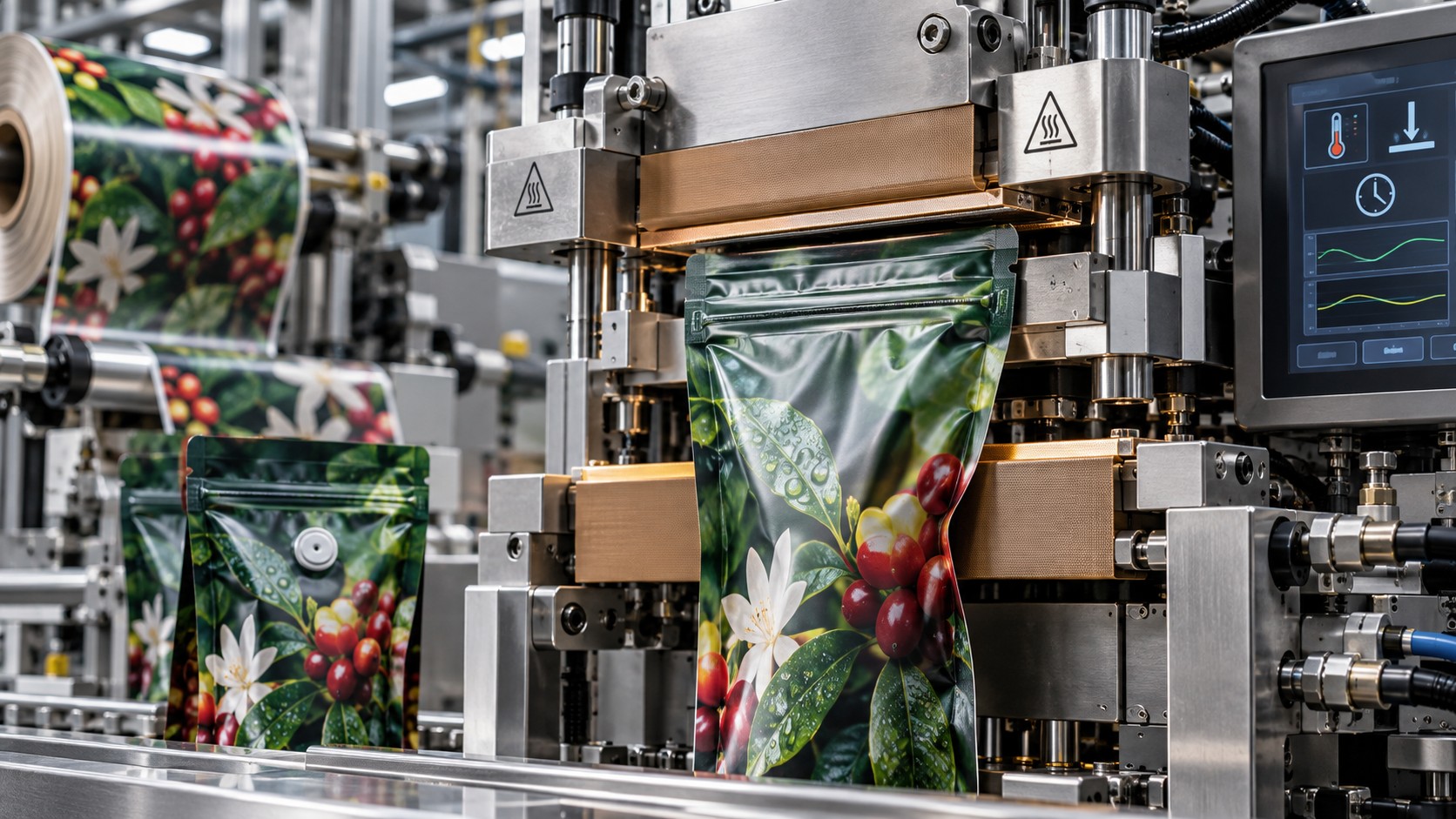
Sealing Is the Final Test: When Heat, Pressure, and Time Determine the Success of Flexible Packaging
Heat Sealing, Pouch-Making, Zippers, Valves, and Digital Print Converting — How Material Construction, Sealing Conditions, Production Speed, and Surface Protection Determine Seal Strength, Package Integrity, and the Quality of Digitally Printed Packaging
BY RONEN DOLEV | 2026
When a Package Is Printed Perfectly, but Sealing Changes Its Color
A digitally printed roll of flexible food packaging arrives at a pouch-making machine. The artwork is colorful, with regions of high ink coverage and a white ink layer beneath portions of the design.
The construction is PET/INK/ADH/PE. Printing was carried out in reverse, and the laminate has completed the adhesion tests and the preparation steps required before converting.
The roll has been slit to the specified width and delivered to a line producing stand-up pouches with a reclosable zipper.
At the beginning of the run, the operator sets the sealing stations according to experience with a similar construction. Temperature, pressure, and dwell time are entered, the cooling stations are adjusted, and line speed is increased gradually.
The first pouches appear acceptable. The seals are continuous, the zipper is positioned correctly, and the package maintains its intended geometry.
But as speed increases, defects begin to appear. Near the zipper, a local color shift develops in the printed image. Elsewhere, the gloss changes. Some pouches exhibit a faint impression of the sealing jaw, and a few show localized separation between laminate layers next to the seam.
The operator increases sealing pressure slightly in an attempt to improve the result. Seal strength improves on some samples, but the gloss variation becomes more visible. Next, the operator raises the temperature to preserve seal strength at higher speed. The problem becomes worse.
The pouches may still pass an initial seal-strength test, yet their visual appearance no longer matches the digitally printed product approved before converting.
This raises an essential question: is the cause the digital ink, the laminate construction, the outer coating, or the sealing process?
An examination of the production sequence shows that the heated jaws contact the outer film surface. In high-coverage regions, heat passes through PET toward the ink and adhesive interfaces below. At the zipper, the material is thicker than at an ordinary side seal, so the heat-transfer requirements are different. Some stations use a textured jaw, while others use a smooth contact surface.
The problem is not merely one incorrect temperature. The process is asking one sealing setup to serve zones with different thicknesses, geometries, and functions without validating the operating window for each zone.
This is one of the central engineering challenges of flexible packaging after digital printing. Digital production makes short runs, rapid artwork changes, and fast delivery of printed reels possible. But after printing, the construction must still withstand heat, pressure, tension, folding, and the attachment of functional components.
The seal is not simply a line where two layers adhere. It is the point at which print quality, film design, material chemistry, and machine engineering are tested together.
Digital Printing Does Not End at the Press
In flexible packaging, the digitally printed job is not complete when the printed reel leaves the printing press. Depending on the product, it may undergo coating, lamination, adhesive curing, slitting, pouch formation, zipper or valve insertion, sealing, and cooling. Only then does it become an empty pouch ready for filling, or a finished, filled package.
Print approval and package approval are therefore different decisions. A printed web may satisfy requirements for color, register, and ink adhesion, while its ink or protective coating still responds poorly to a particular combination of sealing temperature and pressure.
This is especially important with surface printing, where the ink or overprint varnish lies on the outer film face and may directly contact a heated jaw. With reverse printing, the ink is enclosed inside the laminate, yet heat conducted through the exterior film can still affect the ink and adhesive interfaces.
Ink technology also matters. Solvent-dried inks, UV-cured inks, and liquid electrophotographic inks need not respond to heat and compression in the same way. It would be incorrect to claim either that all digital ink systems withstand sealing or that all are inherently unsuitable.
Instead, the ink, substrate, primer where used, coating, and laminate must be qualified as an integrated construction. Room-temperature ink adhesion does not, by itself, demonstrate that the same ink will retain its color, gloss, and adhesion when the package is exposed to a hot sealing jaw.
What Actually Happens During Heat Sealing?
Heat sealing is a process in which two compatible sealable surfaces are brought together under conditions that allow a bond to develop at their interface. In thermoplastic constructions, heating promotes the necessary molecular mobility and interfacial interaction. As the joint cools, the newly formed bond stabilizes and develops its mechanical characteristics.
Heat alone does not define this process. Four variables must be considered together: temperature, pressure, dwell time, and cooling or stabilization. Production speed changes the available contact time and the way the web travels between stations, so it cannot be considered independently of these four controls.
A suitable setup is not a single temperature number. It is a verified operating window within which seal strength, leak tightness, visual appearance, and process stability all remain acceptable under normal manufacturing variation.
Temperature: Why More Heat Does Not Necessarily Mean a Better Seal
The sealing temperature must suit the sealant layer. However, the temperature shown on the machine controller must be distinguished from the temperature actually reached at the interface between the sealable layers.
A controller commonly measures a heater or jaw location. The sealing interface is inside the packaging structure, separated from the jaw by one or more materials. Its temperature can therefore differ substantially from the displayed setpoint.
Heat transfer depends on film thickness, thermal properties, contact time, local pressure, jaw construction, and the number of layers through which energy must pass. At too low a temperature, the sealant may never reach the state required to form a sufficient bond, resulting in weak or discontinuous sealing.
Excessive temperature can produce a different group of failures. The outer layer can distort; softened sealant can flow or be squeezed away from the intended joint; the ink or varnish can exhibit changes in color, gloss, adhesion, or texture; and the lamination adhesive can be damaged if the chosen construction is not thermally suitable.
The goal is not the highest temperature that yields a strong seam. It is the lowest reliably stable sealing window that meets all requirements for strength, integrity, appearance, and production tolerance.
Dwell Time: Giving Heat Enough Time to Reach the Interface
Dwell time is the period during which the jaws contact the material under the conditions required for sealing. It controls how much heat can be transferred from the tool into the sealing interface.
If dwell is too short, the interface may not reach the required conditions even when the jaw is hot. If it is too long, the structure can absorb unnecessary thermal energy, leading to distortion, blocking, jaw marking, or damage to printed and coated layers.
Thicker regions and junctions where several plies overlap often require different heat-transfer conditions from a simple two-ply side seal. This is why a gusset or zipper zone cannot automatically be qualified using settings established for the flat panel.
The answer is not always to raise temperature. Depending on machine capabilities, dwell, the number of sealing stages, jaw geometry, or local seal design may be adjusted. The entire construction must be validated at each functional seam.
Pressure: Establish Contact Rather Than Crush the Construction
Sealing pressure promotes intimate contact between the mating surfaces and supports consistent heat transfer and bond formation. However, higher pressure does not necessarily create a stronger seal.
Insufficient pressure can leave small gaps, particularly around wrinkles, thickness transitions, folds, or multi-ply junctions. Excessive pressure can force softened sealant out of the sealing region, a phenomenon often described as sealant squeeze-out. It can also emboss the outer film, alter gloss, or increase the risk of ink or coating transfer to the tooling.
Why 3 bar on One Machine Is Not Necessarily 3 bar on Another
An indicated pressure of 3 bar may describe the pneumatic pressure supplied to the actuator, not the actual contact pressure on the seal area. The force transmitted to the jaw depends on the actuator and mechanism; the local pressure then depends on the effective contact area and its geometry.
In an idealized uniform-contact model, Contact Pressure = Applied Force / Effective Contact Area. In real equipment, pressure is not distributed perfectly evenly. Jaw parallelism, contact pattern, compliance of the opposing surface, film thickness, and localized transitions all matter.
It is therefore technically unsound to transfer a pneumatic setting from one machine to another without accounting for the tooling and force-transmission system. Qualification should include inspection of jaw straightness, alignment, and parallelism.
Speed: The Process Variable That Changes the Meaning of the Others
Production speed directly influences the sealing operation. On an intermittent line, the cycle must accommodate jaw closing, dwell, opening, and film advancement. Increasing cycles per minute may reduce the available time for each action.
On continuous or rotary sealing equipment, the relationship is different. Effective contact time depends on the contact length and the relative speed of the material and sealing tools. A useful first approximation is: Effective Contact Time ≈ Contact Length / Web Speed.
This illustrates why an increase in speed may reduce the available heat-transfer time. Actual performance still depends on jaw geometry, tool movement, and the machine's control architecture. A nominal line-speed target means little without specifying the equipment and sealing mechanism.
Speed should be increased only after strength, seal integrity, register, and visual stability have been demonstrated at the new operating condition.
Building a Real Heat-Seal Window
A sound engineering approach does not stop at one setting that produces an acceptable first sample. It establishes a heat-seal window.
Start with the verified material structure and precise sealant grade. Select a realistic experimental range using the material supplier's guidance, the machine's capabilities, and the product's requirements. Hold pressure and dwell constant while varying temperature systematically. At each point, evaluate seal strength, failure mode, appearance, and integrity.
Once a suitable temperature band has been identified, investigate dwell time and pressure separately. Finally, validate the resulting window at the intended production speed. Test near the edges of the qualified range as well as at its center.
A very narrow window, in which small changes in speed or temperature cause failures, may not be sufficiently robust for industrial production. A qualified process is defined by a repeatable acceptable range, not one successful demonstration.
A Technical Trial Example: What Published Test Protocols Can Teach Us
A technical guide for digitally printed flexible packaging describes a laboratory sealing-stress protocol using a bench heat sealer. In that specific evaluation, both jaws are heated, pneumatic pressure is set to 4 bar, and dwell time to one second. The guide recommends comparing smooth jaws covered with PTFE and grooved jaws, while testing printed areas with low and high coverage and with and without white ink.
The same guide reports the following jaw-temperature ranges for its specific laboratory test constructions. They are reproduced here as historical protocol examples, not as universal production settings.
Construction | Flat jaw with PTFE | Grooved jaw |
|---|---|---|
PET/PE | 160–190°C | 140–170°C |
PET/AL/PE | 180–210°C | 170–200°C |
BOPP/PE | 140–170°C | 140–160°C |
BOPP/BOPP or BOPP/MET-BOPP | 130–150°C | 130–150°C |
These values belong to a particular laboratory stress test. They do not define the necessary temperatures on an industrial pouch-making machine, and the full thickness and polymer formulation of each sealant layer are not specified in the abbreviated table.
Other constructions, including certain paper substrates carrying dedicated heat-seal coatings, may be evaluated at much lower initial temperatures. These examples do not contradict one another: the materials, sealing mechanisms, tooling, and test purposes are different. Never translate this table directly into machine workpoints without qualification.
Seal Initiation Temperature and Hot Tack
Seal Initiation Temperature (SIT) describes the temperature region at which a specified minimum seal strength begins to develop under a defined test method and acceptance criterion. It is not simply the melting point of the whole polymer construction.
A low-SIT sealant may be advantageous when short dwell is required or when printed layers are heat-sensitive. Yet low SIT alone does not guarantee a sufficiently strong seam at the target production speed.
Hot tack is the strength of the seal shortly after its formation while the joint is still hot. In fast form-fill-seal equipment, the weight of the product or the movement of the package may stress the joint before it has cooled fully. If hot tack is inadequate, the seam may open even though its final room-temperature strength would have been satisfactory.
Cold seal strength and hot tack are therefore different performance characteristics, and both may require validation.
Cooling: Sealing Does Not End When the Hot Jaw Opens
After heating and compression, the sealant can remain warm and mechanically vulnerable. A premature load may deform the seam or pull it apart. Cooling jaws or cooling bars can be essential for allowing the bond and its geometry to stabilize before cutting, stacking, handling, or transfer.
Some pouch-making lines include controlled cooling after longitudinal or transverse seals. The appropriate cooling conditions depend on the construction, machine speed, and product requirements; there is no universal cooling setpoint.
What matters is that the seam retains its strength and shape through the next operation. An effective cooling stage is part of the sealing process, not an optional afterthought.
Pouch-Making Machines Versus Form-Fill-Seal Machines
Although both equipment families produce flexible packages, the process routes differ. A pouch-making machine typically converts rollstock into empty pouches through folding, sealing, component insertion, and cutting; the pouches are subsequently filled on separate equipment.
A form-fill-seal machine integrates package formation, filling, and sealing. Horizontal form-fill-seal (HFFS) and vertical form-fill-seal (VFFS) arrangements serve different products and production requirements.
On an FFS machine, the contents of the package and the timing of filling directly influence the sealing operation. On a pouch-making line, the structural seams may be made and inspected before filling. Even then, the final seal after filling remains a critical operation.
The process specification must state which seams are produced by the converter and which are produced at the packer's plant. The two groups may be made with different tooling, cycle times, temperatures, and product contamination risks.
Seal Geometry: Not Every Seal Is the Same
Fin Seal
A fin seal joins the two inward-facing, sealable surfaces. In PET/INK/ADH/PE, for example, PE can be brought into contact with PE to create the seam. This is suitable for many constructions in which the outer layer is not designed to be heat sealable.
Lap Seal
A lap seal brings the outer face of one portion of web into contact with the inner face of another. If the outside is not sealable, such as an untreated nonsealable PET face, a reliable lap seal may be impossible without changing the construction or applying a qualified sealing layer. The seam geometry must therefore be selected with the chemistry of the mating surfaces in mind.
Side Seal
Side seals connect portions of a pouch, generally through the inner sealant layers. Once the seam reaches a fold or a junction containing several plies, the local thickness and load distribution change, requiring separate validation.
Bottom Seal and Gusset Seal
In a stand-up pouch, a folded bottom panel creates the standing geometry. Junctions may transition between two and four plies, or other combinations depending on the construction. These thickness changes can make heat transfer and pressure uniformity more difficult.
Top Seal
The top seal is often formed after the product has been filled. Powders, crumbs, oils, or liquids may contaminate the sealing area. A seam that performs well on an empty pouch can behave differently under real filling conditions.
Material Construction Defines the Sealant and the Heat Path
The first decision is not a jaw-temperature setpoint. It is the identity of the layer that actually forms the seal.
PET, oriented PP, or aluminum foil may serve as the external layer or a barrier, but they are not necessarily the heat-sealing faces. The joint may be formed with a PE grade, CPP, a purpose-designed coextruded sealing skin, or a specialized heat-seal coating.
Consequently, two structures containing PET may require very different sealing conditions if the sealant compositions differ.
Example construction | Relevant sealant | Qualification focus |
|---|---|---|
PET/INK/ADH/PE | PE | Heat through PET; ink and laminate stability |
BOPP/INK/ADH/CPP | CPP | CPP sealing window and BOPP thermal response |
PET/AL/ADH/PE | PE | Heat-transfer path through an aluminum-containing structure |
PET/AL/ADH/CPP | CPP | Thermal demands, sealant grade, and intended use |
MDO-PE/INK/ADH/PE | PE | Orientation, shrinkage, and process stability |
BOPP/INK/ADH/sealable BOPP | Sealable BOPP face | Suitability of the actual sealing skin |
Paper/heat-seal coating | Dedicated coating | Heat sensitivity of paper, ink, varnish, and coating |
This is a map of engineering considerations, not a temperature-selection chart. Successful qualification identifies the mating layers and the transfer path by which heat reaches them.
Reverse Printing Versus Surface Printing: Why It Matters During Sealing
With reverse printing, the ink is inside the laminate, for example PET/INK/ADH/PE. The jaw usually contacts the external PET face while the ink lies underneath it. The ink is protected against direct mechanical contact, but not isolated from heat. Excessive heat may still affect color, ink adhesion, or lamination interfaces.
With surface printing, ink and perhaps overprint varnish (OPV) are on the exterior. The hot jaw may contact these printed or coated surfaces directly. Depending on the formulation, risks include gloss change, jaw marking, and transfer of ink or coating to the tool.
Surface printing therefore deserves particular attention in thermal and mechanical qualification. Neither an approved room-temperature rub test nor a satisfactory digital print visual inspection is enough to release the package for sealing.
Why High Ink Coverage Changes the Risk
Digital artwork may contain low-coverage areas, saturated builds, multi-color overlaps, and white ink underlayers. A high-coverage region does not necessarily respond to compression and heat in the same way as an unprinted region.
Qualification should therefore sample high- and low-coverage sections, with and without white ink, and relevant coated areas. Evaluate the seal and the printed image together: strength, integrity, color, gloss, and the condition of the ink and varnish films.
Why Does Color Shift Appear in the Sealing Area?
A color change near a heat-seal seam can result from more than one mechanism. The optical appearance of ink or varnish may change under heat and pressure. Changes in outer-film texture, surface gloss, or local laminate geometry can alter light reflection and create the appearance of a color difference without any actual change in the pigment composition.
A local change at an internal interface may also alter the optical properties of a transparent laminate. When a ΔE00 difference is detected, the investigation should distinguish true color change from variation caused by specular reflection, roughness, or measurement geometry.
Compare a sealed sample with an unsealed control from the same printed job under appropriate measurement conditions. Map the defect by station, location, ink coverage, and jaw type. If the effect is restricted to high-coverage regions, that pattern is diagnostic evidence, not proof of one cause.
Why Use PTFE on Heat-Sealing Jaws?
A common method of protecting the package surface during heat sealing is to use a PTFE-based separator or covering. PTFE, polytetrafluoroethylene, is a fluoropolymer with low friction and non-stick characteristics. In packaging equipment, one common product is PTFE-coated glass-fabric tape.
The PTFE cover separates the hot jaw from the exterior surface of the package. Its purpose is not to create the seal—the joint still develops between the package's sealant layers—but to reduce the tendency of the package to stick to the tool, minimize material transfer, and protect the printed surface.
Protecting Ink and Varnish
When a hot jaw contacts a printed or coated face, localized heat, compression, and friction may damage a sensitive surface. A suitable PTFE layer can reduce adhesion and the transfer of material to the jaw.
Reducing Jaw Marks
Jaw texture, contamination, and excessive pressure can imprint a pattern on a pouch. An appropriate PTFE covering can provide improved release properties and help reduce some types of marking. It cannot, however, compensate for warped jaws or fundamentally incorrect pressure settings.
Reducing Material Buildup
Polymer residue, ink, varnish, and other deposits can accumulate on a working jaw. Once contamination forms, it can generate a repeating defect with every sealing cycle. A clean, properly selected PTFE surface may reduce buildup and simplify maintenance.
Does PTFE Change Heat Transfer?
Yes, and this is essential to understand. PTFE is not merely a non-stick coating. A PTFE film or PTFE-coated glass-fabric tape adds thickness and an additional thermal resistance between the heating element and the packaging film.
It can change the rate at which heat reaches the sealing interface. Adding PTFE to a previously bare jaw may therefore require the sealing window to be requalified. Changing from a thinner tape to a thicker grade can alter the result again.
PTFE is not a magic solution that makes excessive temperature harmless. It is a protection element within the heat-transfer system, and it must be considered as part of the process configuration.
When PTFE Becomes a Defect Source
PTFE covers can wear, crease, tear, or become contaminated. An uneven cover can leave an impression on the package or create localized differences in heat transfer and contact pressure. If it wears through, a portion of the hot tool may contact the film directly.
The tape must be installed flat, without folds. Its substrate, coating, thickness, adhesive backing, and rated operating temperature must all be appropriate for the machine. Not every tape that looks similar is suitable for a heat-sealing jaw.
The maintenance SOP should specify cleaning, inspection, and replacement requirements rather than waiting for a finished-packaging defect to appear. On food-packaging equipment, materials used at the tooling interface should also meet applicable safety and cleanliness requirements and should not shed undesirable particles or residues into the production environment.
Smooth Jaws Versus Grooved or Serrated Jaws
A smooth jaw and a grooved or serrated jaw generate different local contact conditions. A textured jaw may concentrate contact pressure differently and can be appropriate for selected sealing applications. Yet when printing lies within the pressure zone, its pattern may leave a visible impression on the package.
For digitally printed structures with high ink coverage or a sensitive OPV, jaw texture is a material qualification variable. Neither a grooved jaw nor a smooth jaw is inherently superior for every application.
Compare the available jaw surfaces under controlled conditions and judge them by seal strength, leak tightness, consistent production, and the visual quality of the printed package.
Sealing a Pouch Without a Zipper
In a pouch without a zipper, the sealing system forms the primary structural seams. A three-side-seal pouch has its own arrangement of three closure seams, depending on when filling takes place. A stand-up pouch has additional bottom geometry, while a pillow pack commonly relies on a longitudinal back seal and transverse end seals.
Each seam is mechanically different. A longitudinal seal may pass its test while a transverse seal fails because the equipment, contact time, and loading differ. At the gusset, a thickness transition may require an additional check.
The correct industrial approach is to validate the different seal stations rather than assume that one acceptable setting represents all zones.
Sealing a Pouch With a Zipper
Adding a zipper changes the sealing problem substantially. A zipper is a polymer profile designed to allow the consumer to open and close the pouch repeatedly. It typically contains two mating profile elements and flange areas that are designed to attach to the pouch film.
The flange must form a reliable bond to the package's sealant surface while the central profile retains its geometry and ability to open and reclose. These are different functions, so heating and crushing the entire zipper indiscriminately is not a sound approach.
Match the Zipper to the Sealant
The first requirement is compatibility between the zipper flange and the package sealant. A PE-based structure typically needs a zipper designed to bond to its PE sealing surface, while PP-based constructions require a suitably matched system.
Compatibility is more specific than the polymer family name. Formulation, additives, thickness, and sealing-skin design all matter. The selected zipper must be qualified with the actual finished laminate.
Why Use More Than One Sealing Station?
Some lines use several stages to attach the zipper. A first station may position and tack the component; another may develop the required flange seal; cooling may then stabilize the assembly.
The actual sequence and number of stations depend on the machine. There is no universal rule that all zipper constructions need the same number of sealing jaws. The objective is sufficient flange adhesion without deformation of the reclosure profile.
Zipper End Crushing
Where a zipper meets the pouch side seals, a substantial thickness transition may occur. Some machines incorporate zipper end-crushing or profile-flattening stations to condition the zipper ends for a continuous side seal.
Depending on equipment and materials, this may involve heat and pressure or another approved joining technology, including ultrasonic methods. Overaggressive crushing can damage zipper functionality or introduce a leak path, so the zipper ends require separate inspection and testing.
Why Does Color Change Near the Zipper?
The zipper region is thicker and may demand different heat-transfer conditions. An operator might respond by increasing temperature or dwell, thereby increasing the thermal exposure of the printed exterior.
A better investigation considers the zipper's sealing range, jaw geometry, the number of sealing stages, and surface protection. In some cases, a zipper compatible with a lower thermal load helps protect the digitally printed image while still achieving a strong flange joint.
How to Verify That the Zipper Has Been Installed Correctly
Two different functions must be tested: the strength of the connection between zipper and pouch film, and the ability of the zipper itself to open and reclose.
Very high flange-bond strength does not prove that the zipper works. Heat- or pressure-induced deformation can make the profile difficult to open or impossible to close correctly. Its end regions and junctions with the side seals must also be examined.
A continuous flange seam may be acceptable along most of its length while a local leak near one end compromises the entire package. Qualification should therefore include bond strength, leak integrity, and repeated opening-and-closing performance.
Packages With Valves: Sealing a Functional Component
A zipper and a valve must not be confused. A zipper provides user-controlled reclosure. A valve is a functional component intended to regulate the passage of gas or other material according to the package design.
A familiar example is a one-way degassing valve for coffee. Freshly roasted coffee may continue to release CO₂ after packing. A suitably designed one-way valve permits gas to leave while limiting air ingress according to its specified performance.
The valve is not a substitute for the oxygen or moisture barrier of the package, nor for a properly sealed seam. It is another critical component of the overall construction.
How Is a Valve Installed?
Depending on valve design and equipment, a hole may first be punched in the film. The valve is positioned accurately relative to the opening and joined to the structure using a process qualified for that valve and laminate.
Some systems use heat sealing. Others may use ultrasonic joining or another validated attachment method. In every case, the surrounding joint must be continuous and sufficiently tight.
An inaccurately located valve can leave a leak path around its perimeter. Too much heat may damage its internal elements, while an inadequate bond can lead to detachment or loss of integrity.
Opening Pressure Is Not Sealing Pressure
Two different pressures must be distinguished. The sealing machine's pressure is the mechanical force system that attaches the valve to the pouch. The valve's opening pressure is the differential pressure at which its functional mechanism begins to pass gas.
These are unrelated performance measures. A valve may be attached securely yet fail to operate correctly if the internal mechanism has been distorted during installation.
Valve Qualification
Qualification should confirm attachment strength, integrity of the perimeter joint, and controlled gas release under the specified conditions. The valve should also limit reverse gas ingress as required by the application. Where the product contains powder or fine particles, consider whether contamination can interfere with valve operation.
Use the valve supplier's test protocol and the packed product's performance specification; do not substitute a single generic heat-seal setting or peel test for full functionality.
A Valve Is Not a Spout
Flexible packages can also include spouts that enable filling or dispensing of the product. Although both spouts and valves are attached to a pouch, they serve different functions.
A one-way valve manages the flow of gas. A spout generally permits the product to move into or out of the package. A spout joint must connect the rigid or semi-rigid component to the pouch sealant, often around a complex three-dimensional geometry.
Dedicated tooling may therefore be needed to match the spout profile. Attachment strength and integrity should be tested after realistic filling, squeezing, drops, or other use-related stresses.
Sealing Paper-Based Structures After Digital Printing
Paper-based flexible packaging presents its own challenges. Paper alone is not necessarily heat sealable. A usable construction may include an internal PE layer or a dedicated heat-seal coating. Examples include paper/PE laminates and paper structures coated with functional sealant layers.
When digital surface printing is applied to the paper exterior, the hot jaw may contact the printed image directly. Local changes in color, gloss, and ink adhesion are possible if thermal or mechanical resistance is inadequate.
A suitable heat-resistant OPV can offer protection in certain constructions, but its compatibility with ink, sealing conditions, migration requirements, and intended use must be evaluated.
What Happens Where Four Layers Meet?
In a pouch with a folded bottom, the local thickness may increase at the junction of several plies. A jaw setting established on a two-layer area may not transfer adequate heat into the inner interface at the thicker junction.
The instinctive response is often to raise the overall temperature. That can damage the thinner regions. Instead, consider a dedicated station, appropriately shaped tooling, or multiple sealing actions if the machine and construction support them.
The aim is to achieve integrity at the thickest joint while preserving the appearance and functionality of the most sensitive printed area.
Why Surface-Printed Packaging May Need a Heat-Resistant OPV
A protective overprint varnish can improve resistance to abrasion, handling, and certain thermal exposures, depending on its formulation. But not every OPV is suitable for direct contact with a heated jaw.
A high-gloss coating may change appearance under combined heat and compression. Additives that affect slip or surface properties may also influence friction or adhesion. OPV selection for a heat-sealed package must therefore include the converting process, not only print aesthetics.
Evaluate thermal resistance, surface stability after sealing, and adhesion to the underlying ink. Where the design permits and the process requires it, unprinted or uncoated zones may be used. Where printing must remain in the jaw-contact area, qualify the ink–OPV–substrate system under the actual machine conditions.
What Constitutes an Acceptable Seal?
An acceptable seal is defined by the intended application, not by appearance or strength alone. Several performance terms must be kept separate.
Seal strength is the force needed to separate a joint under specified test conditions. Seal integrity is the absence of unacceptable leak paths. Hot tack refers to strength before full cooling. Visual stability means the sealed package retains an acceptable printed and coated appearance. Functional performance covers behavior during filling, shipment, storage, and consumer use.
A seal can have high measured peel strength yet contain a small channel leak. A pouch may be tight during initial inspection but fail after a drop or mechanical loading. A valid release decision must combine the tests appropriate to the package and the risks of its use.
ASTM F88: Measure Strength and Identify the Failure Mode
ASTM F88/F88M describes the measurement of seal strength for flexible barrier materials. A specimen of known width is separated using defined equipment and test conditions. Results may be reported as force per specimen width, for example N/15 mm, depending on the protocol.
The numerical result alone is not enough. Identify whether the seal peeled apart at the intended interface, whether a film layer tore, whether lamination delaminated, or whether substantial stretching occurred before separation.
Different failure modes indicate different possible causes. A useful Seal Bond Strength (SBS) report records the specimen dimensions, conditioning, test method, machine settings, strength value, and failure mode.
There is no universal SBS pass value for every pouch. Required strength depends on package dimensions, filled product weight, filling process, distribution, and end-use conditions.
Leak Testing: Seal Strength Is Not a Leak Test
Where the package protects a product against oxygen, moisture, or external contamination, integrity testing is essential. ASTM F3039 provides a dye-penetration method for detecting certain leak paths in nonporous packaging and flexible barrier materials, within its applicability limits.
Other tests—including internal pressurization and bubble methods—can detect suitable classes of larger leaks. Vacuum-decay and other technologies may be applicable when validated for the packaging format and sensitivity required.
Destructive and nondestructive methods should be distinguished. No single integrity test suits all materials, package dimensions, or sensitivity requirements. Selection follows the product's risk assessment and specification.
Troubleshooting: Temperature, Pressure, Dwell, and Speed
Symptom | Possible causes | First diagnostic actions |
|---|---|---|
Weak seal | Temperature too low, dwell too short, inadequate contact | Build a seal curve; record failure mode |
Passes at slow speed but fails at target speed | Reduced effective contact time | Check cycle timing, sealing stages, heat transfer |
Wrinkles at seam | Web tension, jaw alignment, folding geometry | Inspect web path and jaw parallelism |
Sealant squeeze-out | Excessive heat or pressure | Review compression and sealing window |
Jaw marks | Jaw texture, deposits, excessive pressure | Inspect cleanliness, PTFE, contact geometry |
Gloss change | Thermal load, pressure, OPV, jaw surface | Compare smooth jaw, PTFE, thermal settings |
Printed color shift | Heat, ink coverage, layer structure | Compare printed control areas and seal zones |
Ink or OPV lifts to the jaw | Inadequate thermal resistance or adhesion | Check coating, ink, temperature, PTFE |
Seal opens before cooling | Inadequate hot tack or early loading | Evaluate cooling and transfer timing |
Repeated impression at a fixed pitch | Damage or deposits on jaw or PTFE | Inspect the corresponding tooling location |
Troubleshooting: Zipper, Gusset, Valve, and Spout Zones
Symptom | Possible causes | First diagnostic actions |
|---|---|---|
Leak beside zipper | Material mismatch or weak attachment | Inspect flange, zipper ends, attachment settings |
Zipper difficult to open | Profile distortion from heat or pressure | Check end crushing and jaw geometry |
Zipper cannot reclose | Damaged profile or misalignment | Test function after repeated use |
Color change by zipper | Extra heat to compensate for local thickness | Review stations and printed-surface protection |
Tunneling beside zipper | Weak laminate bond or thermal stress | Measure laminate bond and locate failure plane |
Gusset leak | Multi-ply junction or unequal contact | Inspect thickness transitions and dedicated tools |
Valve detaches | Incompatible joint or insufficient attachment | Test bond and joining method |
Leak around valve | Misaligned opening or incomplete perimeter bond | Inspect position and perimeter integrity |
Valve fails to open | Internal damage or unsuitable component | Test specified opening pressure |
Valve admits excess air | One-way mechanism failure | Test reverse-flow performance |
Case Study: Color Shift on a Digitally Printed Pouch Seal
Consider a reverse-printed PET/INK/ADH/PE pouch intended for a food application. Ink adhesion and laminate bond strength meet specification, but a localized color change appears after pouch-making.
The investigation should begin with a defect map. Does the color shift occur at every seal or only one station? Is it restricted to high-coverage image areas? Is gloss affected as well as hue? Does the defect occur with a smooth jaw, a textured jaw, or both?
Conduct a controlled comparison of sealed samples at different process settings. Change one major variable at a time. A reduction in temperature, a dwell adjustment, or a suitable PTFE jaw cover may reduce the visual change, but only if SBS and seal integrity remain acceptable.
If a different OPV or material construction is needed, requalification is required. Before changing the ink or primer, establish whether the primary cause is jaw contact, thermal load, or the printed layer's actual resistance.
The goal is not simply a strong seal. It is a strong, integral seal that preserves the approved digitally printed appearance.
Case Study: Digitally Printed Coffee Pouch With Zipper and Valve
Consider a digitally printed high-barrier coffee pouch that includes a reclosable zipper and a primary hermetic top closure above the zipper. A one-way degassing valve allows carbon dioxide to escape under its specified operating conditions.
Several distinct joints must be qualified. The structural seams must carry the pouch's mechanical loads. The zipper flanges must be attached to the sealant while its interlocking profile remains functional. The valve must be joined without compromising its one-way mechanism. The top seam must be created reliably after coffee filling.
If a leak is detected, locate it before adjusting the machine. Near the zipper, examine flange adhesion and its ends. Around the valve, examine the perimeter bond and the mechanism itself. At the top seam, investigate sealing parameters and possible contamination by coffee particles.
A single SBS result cannot qualify this construction. Separate acceptance criteria are required for the structural seals, zipper attachment, repeated reclosure, valve function, and the filled finished pack.
Case Study: Digitally Printed Paper Pouch With Heat-Seal Coating
Consider a dry-food package built with paper and a suitable heat-seal layer. The paper exterior is digitally surface printed, with high-coverage regions protected by a selected overprint varnish.
In early trials, seal strength is satisfactory but the hot jaws leave marks on the image. The operator installs a suitable PTFE covering. Sticking and marking decrease, but the measured seal strength changes. The additional PTFE layer has altered heat transfer, requiring a new sealing-window study.
The qualification must also include folded regions where the number of paper plies increases. Settings adequate for two layers may not be sufficient for a four-ply transition. Conversely, conditions optimized only for the thickest area may overheat the thinner printed zones.
The engineering task is to obtain a tight joint at the most difficult thickness transition without sacrificing visual quality at the most thermally sensitive printed region. The solution is an integrated material-and-tooling design, not merely a different varnish or more tape.
How to Qualify a Sealing Machine for Digitally Printed Packaging
For a new flexible-packaging construction, work backward from the finished package rather than forward from the digital press. First define the packed product, filling conditions, integrity needs, pouch geometry, and any functional accessories.
Select the film construction and sealant formulation. Define whether the image is reverse printed or surface printed and identify where printed layers, primer, adhesive, or OPV will encounter heat and pressure. Map every seal zone against the artwork before committing to design or production.
Specify the equipment family, jaw construction, jaw surface texture, and any PTFE covering. Establish the basic window for ordinary seams, then separately qualify gussets, zipper attachments, valves, and spouts where applicable.
Evaluate strength, integrity, hot tack where necessary, and the appearance of the printed package. Increase production speed in controlled steps and confirm that the process remains within its operating window.
Finally, test representative finished pouches, filled when relevant, under conditions simulating the intended application. The desired output is a repeatable industrial process—not an isolated successful sample.
Sealing and Pouch-Making Qualification Card
Every qualified construction should have a documented workpoint and acceptance record. Record the complete layer structure and thicknesses, sealant grade, printing method, digital ink family, primer if applicable, lamination route, and protective coatings.
Document the pouch-making or form-fill-seal machine, jaw types, jaw-contact geometry, and the position of the sealing stations. For each station, record temperature setpoints and measurement locations, dwell time, pneumatic setting and/or actual contact-force information, production speed, and cooling conditions.
If PTFE is fitted, document its product type, thickness, installation requirements, and inspection or replacement schedule. For a zipper, valve, or spout, record the exact component specification and attachment method.
Define acceptance criteria for SBS, seal integrity, hot tack where relevant, visual stability, ink and varnish performance, and functional-component testing. The approved process window should include controlled operating limits and an escalation route for failures.
Specify which changes require requalification. Changes to sealant formulation, layer thickness, ink system, OPV, zipper grade, valve type, PTFE thickness, jaw surface, or sealing machine may alter the approved window even when the artwork looks identical.
Sealing Is Not Merely the Final Step—It Is Where the Whole Process Is Tested
In digital flexible-packaging printing, substantial effort goes into image quality, color management, material choice, primer performance, ink coverage, and white-ink consistency. But a perfect print does not guarantee a successful package.
Ultimately, the printed film must become a three-dimensional construction that contains the product and protects it throughout its life. Sealing applies heat and pressure to a system that has already been printed, coated, laminated, and converted. Each layer has a different job.
The sealant must form a bond. The barrier layer must remain intact. The laminate adhesive must withstand the thermal load. Ink and OPV must retain adhesion and appearance. The zipper must remain operable. The valve must preserve its one-way function. And the seams must stay tight after filling, distribution, and storage.
When a sealing defect appears, the first response should not automatically be to raise the temperature. Determine the construction, identify the intended sealing faces, and trace the heat-transfer path to them. Establish the effective dwell, applied contact conditions, line speed, cooling behavior, and the characteristics of any PTFE jaw covering.
When color changes in the seam region, investigate the ink and OPV together with jaw texture and thermal load. When leaks develop beside a zipper or valve, examine the local attachment geometry and the function of the component itself.
Higher temperature is not necessarily better sealing. Higher pressure is not necessarily a stronger joint. Higher speed is not automatically more efficient production. And a seam that meets its SBS target is not necessarily leak-tight, visually acceptable, or fit for use.
True success is a package whose seams are strong, tight, and consistent, whose functional components work, and whose digitally printed image remains exactly as approved.
The customer does not buy only a printed roll. The customer buys packaging that protects the product, preserves its quality, and presents it correctly. Heat sealing is where those promises must become reality.
Professional References and Further Reading
- ASTM F2029 — Standard Practices for Making Laboratory Heat Seals for Determination of Heat Sealability of Flexible Barrier Materials.
- ASTM F88/F88M-23 — Standard Test Method for Seal Strength of Flexible Barrier Materials.
- ASTM F1921/F1921M — Standard Test Methods for Hot Seal Strength (Hot Tack) of Thermoplastic Polymers and Blends.
- ASTM F3039-23 — Standard Test Method for Detecting Leaks in Nonporous Packaging or Flexible Barrier Materials by Dye Penetration.
- ASTM F2096 — Standard Test Method for Detecting Gross Leaks in Packaging by Internal Pressurization.
- 3M — Technical specifications for PTFE-coated glass-cloth tape used in heat-sealing and packaging equipment.
- Ronen Dolev (2026), Flexible Packaging Application — Technical Training Deck. Uploaded supporting material; especially the sections on pouch-making, SBS, sealing windows, and visual defects.
- Flexible Packaging How-to Guide, Technical Edition (January 2017). Uploaded supporting reference; especially Pouch Making / Sealing, Sealing Stress Testing, and Troubleshooting. Its numerical values apply to specific test protocols and constructions, not universal production settings.
- Plitek — Degassing Valves for Coffee Packaging: Technical Application Overview.
- TricorBraun Flex — One-Way Degassing Valves for Flexible Packaging: Technical Overview.
Technical note: Sealing temperatures, pneumatic pressures, actual contact loads, dwell times, line speeds, PTFE grades, cooling conditions, and SBS acceptance criteria depend on the package construction, sealant formulation, digital ink and coatings, equipment, and end-use requirements. The example ranges in this article must never be used as direct machine settings without qualification of the specific construction.