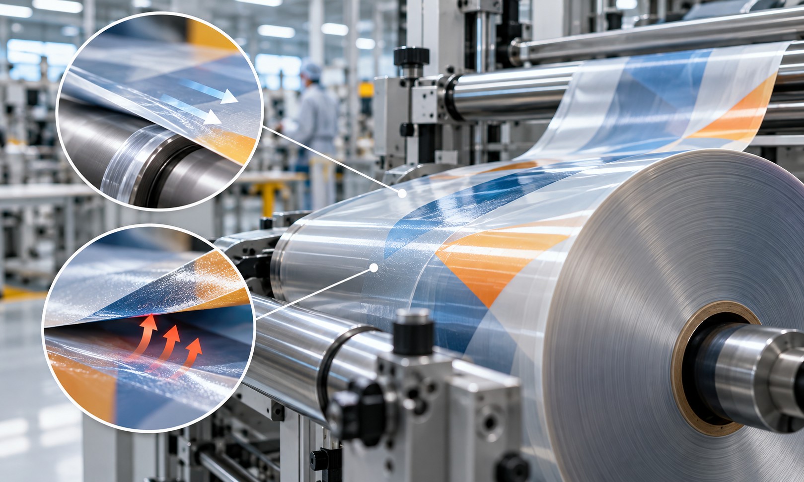
The print passed every inspection. Why does the package still fail on the machine?
A roll of flexible packaging arrives at a filling and packaging machine after successfully passing production quality checks. Color matches the approved target, ink adhesion is acceptable, the laminate meets its bond requirements, and the roll appears uniform. Yet as soon as production begins, the web doesn't move smoothly. Tension fluctuates, wrinkles form around the forming section, and the machine stops intermittently.
Operators inspect rollers, guides, and machine settings. The fault looks mechanical until another roll runs without difficulty. Elsewhere, the opposite problem appears: the film is so slippery that pulling rollers cannot consistently control its position, or finished packs slide excessively when stacked.
Both cases can be associated with the coefficient of friction, commonly called COF. This property does not determine color accuracy, ink adhesion, or laminate bond strength, but it can determine whether an otherwise acceptable printed structure runs successfully through converting, filling, sealing, and distribution.
What is COF, and why does friction occur?
The coefficient of friction is the ratio of the friction force resisting relative motion between two surfaces to the normal force pressing them together. It is dimensionless. A higher COF generally means greater resistance to sliding under the tested conditions; a lower COF generally means easier sliding.
COF is not a permanent property of one material in isolation. It characterizes a particular pair of contacting surfaces under specified conditions. A PET film may behave differently against another PET film, polished steel, rubber, or a coated guide. Even the two sides of the same packaging film can have markedly different frictional behavior.
Real surfaces are not perfectly smooth. Microscopic asperities contact one another, and intermolecular adhesion develops at contact points. During motion, energy is consumed overcoming these interactions and local deformation. For flexible polymers, surface chemistry, mechanical compliance, and viscoelastic behavior all influence the measured force.
The result depends on the substrate, contact surface, print coverage, coating composition, additives, pressure, measurement speed, temperature, humidity and storage history. Therefore, it is essential to describe exactly what was measured.
Static COF versus dynamic COF
Static COF characterizes the resistance that must be overcome to initiate sliding when the surfaces are initially at rest. Dynamic COF, also called kinetic COF, characterizes friction during ongoing relative motion. In many material pairs, the static value is higher than the dynamic value, but this relationship should not be assumed for every construction.
Packaging machines operate through combinations of starts, stops, acceleration, and steady transport. Static friction matters as motion begins; dynamic friction matters once the material is moving. When the transition between sticking and sliding becomes unstable, a stick-slip response may develop. Depending on machine dynamics, this may contribute to jerky feed, web-tension fluctuations, or positioning errors.
For this reason, an approval report should distinguish static and dynamic values rather than reporting a single unlabeled COF number.
Why COF matters throughout packaging production
In printing, COF can influence contact between the web and handling components, winding behavior, and the movement of printed sheets. During slitting and converting, it can affect web separation and transport. In vertical or horizontal form-fill-seal equipment, the film slides against forming shoulders, guides, and contact surfaces while other components depend on adequate grip to pull it forward.
Excessive friction against a forming component may raise web tension and contribute to wrinkles or machine stops. Too little friction at a traction point can allow slippage and reduce registration stability. After packaging, excessively slippery external surfaces may compromise stacking and pallet stability, whereas high friction can hamper product separation and feeding.
The engineering goal is therefore not the lowest possible COF. It is a controlled friction range suited to each contact surface and each stage of the production process.
How substrate selection changes friction
PE and PP films frequently contain additives formulated to adjust slip or block resistance. Their mechanical behavior, surface texture, and extrusion conditions also affect friction. PET films may behave differently depending on surface treatments, coatings, and roughness. Multilayer packaging constructions can present different properties on their external and sealant sides.
The outermost layer often dominates contact with machine components, but additives originating in other layers may migrate over time and modify the accessible surface. The direction of testing can also matter when a film has anisotropic surface features. Material qualification should therefore specify the complete structure, the tested side and the opposing contact material.
Slip additives: how film becomes easier to move
Slip additives are used to reduce friction between surfaces. Some common migrating slip systems use fatty-acid amides, including oleamide and erucamide. When incorporated into a polymer matrix, these materials can gradually migrate toward the surface and form a thin layer that changes interfacial interactions. The migration is often described as blooming.
This mechanism can reduce COF without fundamentally changing the bulk mechanical construction. Its limitation is time dependence: a film tested immediately after manufacture may differ after days of storage. Migration rates depend on additive chemistry and concentration, polymer formulation, temperature, multilayer structure and conditioning history.
Other, more permanent or low-migration slip approaches also exist. Selecting a slip system requires balancing machine performance, long-term stability, and compatibility with printing, coating, adhesive bonding, and sealing operations.
Can slip additives damage printability or lamination?
They can. Migrating additives alter the chemistry of the accessible surface and may change wetting behavior and interactions with ink, primer or adhesive. In unfavorable combinations, a mobile surface layer can contribute to poor ink adhesion, inconsistent coating, or reduced laminate performance.
Increasing the slip-additive concentration to address a high-friction web may therefore resolve transport problems while creating another failure in printing or converting. The right strategy is to qualify the additive package as part of the complete packaging structure and verify COF alongside wetting, print adhesion, bond strength, and seal performance.
Do not assess a slip additive independently of the final production sequence. Aging, heat exposure, corona treatment and lamination can all influence the outcome.
Blocking: a related problem, not the same measurement
Blocking occurs when adjacent layers adhere unintentionally after prolonged contact, especially under pressure, heat, or storage time. Very smooth polymer films can have extensive real contact area; tacky or insufficiently stabilized ink and coating layers can also contribute to blocking under certain conditions.
Antiblocking additives often use fine particles to create microscopic separation between surfaces and reduce the true contact area. These additives primarily improve layer separation. Slip additives primarily influence sliding resistance. Both may be used in the same film, but their effects and performance tests must be distinguished.
Property | Primary purpose | Desired practical outcome |
|---|---|---|
Slip | Reduce resistance to sliding | More controlled, lower-friction transport |
Anti-slip | Increase grip where required | Stable stacking or reliable traction |
Antiblocking | Reduce adhesion between contacting layers | Reliable unwinding or film separation |
A package may require low friction on its sealant side and higher grip on its external side. Multilayer design can deliberately create different surface behaviors to meet those demands.
How digital printing affects COF
In digital printing systems that leave an ink layer at the substrate surface, the ink binder, coverage, surface texture, and layer structure can change friction behavior. An area with full solid coverage may have a different COF from an unprinted area or a region with sparse tone values. Additional opaque white layers or multiple color layers can also modify surface contact and thermal response, depending on the technology and ink chemistry.
It would be incorrect to assume that digital printing always raises or always lowers COF. The final effect must be measured for the specific film-and-ink combination. A thermoplastic printed layer, for example, may show different friction characteristics under heat and pressure than at room temperature.
When the printed web is reverse-printed and then laminated, the commercial product's external contact surface may be the laminating film rather than the ink. In that case, the exposed film surface usually more directly determines friction against downstream machine components.
What changes in offset, flexography and gravure?
Conventional printing presents the same underlying friction mechanisms, although coating compositions and process structures differ. In sheetfed offset, ink coverage, drying, varnish, and the paper or board surface can influence sheet movement and stacking. In flexography and gravure, resin chemistry, dried-film thickness, topcoats and converting conditions affect the exposed surface.
A reverse-printed, laminated flexible package generally exposes a polymer film to the converting machine rather than the print layer. A surface-printed package, by contrast, may expose ink or varnish directly to guide rollers and adjacent layers. The location of the final printed or coated surface is often more significant than the distinction between digital and conventional printing alone.
Varnishes and coatings are also friction-control layers
Varnish is not merely a gloss or protective finish. Its resin system, waxes, slip additives, fillers, curing conditions, and microscopic texture can alter COF. Two varnishes with similar gloss can behave differently in transport; you cannot rank matte and glossy finishes for friction based on optical appearance alone.
Water-based and radiation-curable varnishes can achieve different friction profiles depending on formulation and process conditions, but curing technology alone does not determine friction. Measure the coating after drying or curing is complete and verify abrasion resistance alongside the required COF. A coating that solves friction but fails rub durability is not an acceptable production solution.
Why lamination can change the final COF
Flexible packaging often contains an outer printable layer and an inner sealant layer. Each side can require a different coefficient of friction. During and after lamination, additive migration, layer interactions, adhesive curing, and thermal history may change the final surface characteristics.
Consequently, a COF result from an unlaminated film does not necessarily represent the finished package. Test the final construction after the prescribed curing period and, where migrating slip additives are involved, repeat testing after a defined storage interval. Test both external and internal surfaces against the contact materials relevant to the actual machinery.
What COF values should be specified?
Industry literature sometimes uses approximate categories for plastic films: low friction at or below 0.20, intermediate friction from 0.20 to 0.40, and relatively high friction above 0.40. These are descriptive guideposts, not pass/fail limits set by measurement standards, and not universal targets for every packaging machine.
COF value | General interpretation | Important qualification |
|---|---|---|
Up to 0.20 | Low friction / high slip | May be useful for sliding contact but too slippery for traction or stacking |
0.20–0.40 | Intermediate friction | Often investigated during application development; not a universal target |
Above 0.40 | Relatively high friction | May support grip but increase drag at certain guides or forming surfaces |
A COF of 0.18 may suit one forming surface while causing slip at another traction point. A value of 0.45 may be undesirable for sliding transport yet useful where stable pack stacking is required. Always establish acceptable ranges based on the target application, material pair, machine conditions, and customer specification.
How to write a useful customer COF specification
A meaningful specification contains more than a number. It identifies the contacting surfaces (such as film-to-film or film-to-metal), the tested side, static and/or dynamic COF, the chosen method, conditioning, test speed, sample age, and the point in production at which the sample is taken.
For illustration only, a project might set a dynamic film-to-defined-metal target of 0.20–0.35, with a different range for sealant-side film-to-film contact. This example must not be treated as an international-standard limit or adopted without qualification on the actual forming and pulling equipment.
The specification should also state whether measurement is required immediately after film manufacture, after printing, after lamination and curing, or after a defined storage time. When migrating slip additives are present, measurement timing may materially affect acceptance.
How COF is measured
Laboratory COF testers typically place defined contacting surfaces under a controlled normal load and measure the force needed to initiate and maintain relative motion. A sled-type arrangement is common: the specimen and opposing material are secured to the relevant parts of the test apparatus, and a specified relative motion is applied.
Use the measured starting and sliding forces to determine static and dynamic coefficients. The film orientation, opposing surface, sled mass, speed, and environmental conditions must follow the method and agreed specification.
ISO 8295:1995 provides a method for plastic film and sheeting. ASTM D1894-24 provides a method for static and kinetic coefficients of friction of plastic film and sheeting. Although both address COF, results are not necessarily directly interchangeable because the procedures and apparatus conditions can differ. ISO 15359 applies to paper and board, while ASTM D3354 addresses blocking force rather than ordinary sliding friction.
Standard | Main application | Measurement purpose |
|---|---|---|
ISO 8295:1995 | Plastic film and sheeting | Static and dynamic friction in defined test arrangements |
ASTM D1894-24 | Plastic film and sheeting | Static and kinetic coefficients of friction |
ISO 15359:1999 | Paper and board | Static and kinetic friction using the specified horizontal method |
ASTM D3354-21 | Plastic film | Blocking load/separation resistance |
What belongs in a COF test report?
A usable report records the test method and revision, specimen identity, structure, tested side, contact pair, sample-conditioning conditions, temperature, humidity, measurement speed, sample age, and the processing stage. It should state static and dynamic COF separately, identify the number of replicates, and report variation in the data.
For wide webs, it may be appropriate to sample the edges and center and investigate change along the roll. Significant spatial variation may point to nonuniform coating, additive distribution, print coverage, or processing conditions. Use repeat measurements rather than relying on a single result.
Why COF changes after production
In many polymer systems, COF is not fixed at extrusion or coating. Migrating slip agents continue to redistribute, and curing or drying can change the exposed layer over time. Winding pressure, storage temperature, and other environmental conditions influence contact between film layers and may contribute to blocking.
When investigating a complaint, compare samples of similar age and storage history from the same production batch. A freshly produced film and a roll stored for several weeks should not automatically be treated as equivalent specimens.
COF, surface energy, and static electricity are different properties
These three subjects are often confused because they can all affect web handling and converting. Surface energy influences wetting and how ink, primer, or adhesive interacts with the substrate. COF describes resistance to relative sliding of two contacting surfaces. Static electricity describes electric-charge separation and accumulation.
A film may have acceptable wetting characteristics and either high or low COF. A film with acceptable COF may still accumulate enough electrostatic charge to attract dust or disturb handling. Before attributing a machine-feed fault to friction, investigate electrostatic charge, web tension, thickness uniformity and mechanical adjustment where relevant.
Preventing COF failures during package development
Prevention starts with describing how the film will move through the actual packing line. Identify which surfaces contact forming shoulders, fixed guides, pulling rollers, and adjacent film layers. Determine whether the outside needs higher grip for stacking while the inside needs easier sliding or separation.
Choose the film construction, slip system, and coatings accordingly, while confirming that any additive or coating adjustment does not compromise print adhesion, lamination bonding, sealing, food-contact compliance, or other application requirements. For rolls that remain in storage before use, define aging tests as part of qualification.
Ultimately, run a trial on the intended packaging machine. The laboratory COF result is valuable but does not reproduce every aspect of machine geometry, speed, temperature, and contact pressure.
Troubleshooting: when COF is out of specification
Observed problem | Possible root cause | Verification | Corrective direction |
|---|---|---|---|
Film sticks at a forming shoulder. | High friction, high local pressure, or unsuitable tension | Dynamic COF against the actual contact material; inspect guides and tension | Adjust structure/coating or contact geometry after isolating the cause |
Film slips and registration drifts | Too little grip at traction point or a mechanical-control issue | Static/dynamic COF and drive/tension system checks | Balance friction and pulling control |
COF changes after storage | Slip-additive migration or surface aging | Retest at defined aging intervals | Use a more stable additive package or adjusted construction |
COF shifts after printing | Ink-layer texture, composition, or coverage | Compare unprinted and printed areas | Review ink, coverage, and exposed finish |
COF changes after varnish | Coating formulation or incomplete curing | Measure before/after coating and after full cure | Adjust coating and curing process |
COF changes after lamination | Film surface, slip migration, or adhesive-curing effects | Test completed structure after cure | Review construction and processing sequence |
Unwinding requires excess force. | Blocking from pressure, heat, or tack | Dedicated blocking measurement | Review antiblock package, winding and storage |
COF varies across web width | Uneven coating or additive distribution | Map results at edge/center/edge | Correct upstream process uniformity |
Print adhesion declines after adding slip | Mobile additive at ink-contact surface | COF, wetting and print-adhesion testing | Rebalance additive system and surface preparation |
Finished packs slide in stacks. | External COF too low | Pack-to-pack friction/stacking trial | Adjust outside surface for grip |
Engineering case: a good laminate fails on a horizontal packaging machine
Consider a printed laminate with an external film and an internal sealant film. At the end of converting, ink adhesion, bond strength, and sealing tests all pass. The initial COF also falls within the declared acceptance range. After several days in storage, however, the roll causes tension variations and inconsistent movement through a horizontal forming station.
A repeat COF test shows a change from the original value. Before changing machine settings or rejecting the material, the investigation evaluates the slip-additive package, migration over time, storage conditions, and the exact surfaces contacting the machine. It also checks whether the measurement was taken before the adhesive fully cured or the film equilibrated.
If additive migration is responsible, an adjusted film formulation or more stable slip approach may be needed. If measured COF remains compliant while transport still fails, the team should investigate film tension, traction rollers, guide condition, and forming geometry rather than assigning the fault to friction alone.
The case illustrates why one passing COF measurement at the end of converting cannot guarantee trouble-free performance weeks later.
Building a process-wide COF quality-control plan
At incoming inspection, confirm the film structure and the COF that matters to printing and converting. After printing, test again when exposed ink may alter the contact surface. Following varnishing or lamination, test the completed structure after the required curing or drying stage. When migrating additives are used, add measurements after defined storage periods.
Associate every result with the contact pair, test method, conditioning, sample location, and sample age. Establish a clear response to nonconformity: first rule out testing error, then distinguish time-dependent change from a genuine formulation or production shift. Only after the root cause is identified should the substrate, additive, ink, coating or process setting be changed.
Conclusion: the next production stage is the real test
Color accuracy, ink adhesion and laminate bond strength are essential quality indicators, but none alone guarantees that printed packaging will move, separate, feed and stack correctly. COF affects every stage where surfaces contact and move relative to one another, and its value can change with formulation, printing, coating, curing, and storage.
Excessive friction can cause drag, wrinkles and stoppages; friction that is too low can undermine traction and stable stacking. Measure blocking separately, and don't confuse friction with surface energy or electrostatic charging.
For digital and conventional printing alike, the objective is not to produce the lowest COF but to engineer the right friction behavior for each pair of surfaces and each production step. A product is truly successful only when it performs reliably after it leaves the printing press and enters converting, filling, packaging and distribution.
Technical standards and further reading
The standards below provide measurement frameworks. They do not establish one universal target COF for all package structures or machines.
- ISO 8295:1995 — Plastics: film and sheeting; determination of the coefficients of friction
- ASTM D1894-24 — Static and kinetic coefficients of friction of plastic film and sheeting
- ISO 15359:1999 — Paper and board; determination of static and kinetic coefficients of friction
- ASTM D3354-21 — Blocking load of plastic film by the parallel plate method
- Modifying the Slip of Plastic Films with Additives — Plastics Engineering (2025)
- How Printability of Polyethylene Packaging Films Containing Surface Additives Is Influenced by Corona Treatment — Journal of Vinyl and Additive Technology
- A Study of Polyethylene Packaging Films in Presence of Slip-Agent and Anti-Block Additives — Polymer Engineering & Science (2025)
- Study of Inorganic-Based Anti-Blocks as Migration Control of Slip Additive on Surface Polyethylene Monolayer Film — Acta Chimica Asiana