The Label Looks Perfect. So Why Does It Fail? When Converting Determines Label Quality
Die-Cutting, Kiss-Cutting, Punching, Matrix Stripping, Slitting, Rewinding, and Label Application — How Knife Selection, Adhesive Construction, the Release Liner, and Process Control Determine Whether a Label Works on the Product
By Ronen Dolev
When the Label Is Perfect, but the Application Line Stops
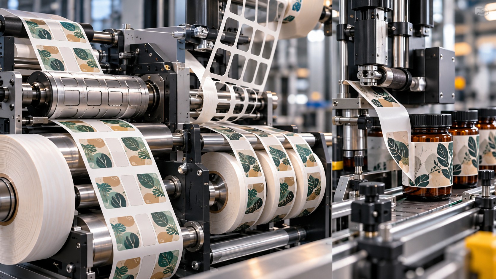
A printed label roll leaves the printing press. Colors are accurate, registration is correct, the varnish is uniform, and the metallic embellishments are exactly where the artwork specifies. All print-quality checks have passed.
The labels are printed on transparent PP film with a pressure-sensitive adhesive and a transparent polymeric release liner. The liner carries them through production and transport until they are applied to the product.
After printing, the roll undergoes rotary die-cutting. The knives cut each label's shape, the surrounding waste is removed by matrix stripping, and the material is slit and rewound to match the customer's applicator specifications. On visual inspection, everything looks right. The edges are clean, matrix removal is complete, the gaps between labels are regular, and the roll meets the stated dimensions.
But on the customer's application machine, faults begin. Some labels fail to release from the liner. Others hesitate at the dispensing point. Occasionally the liner tears and the machine stops.
The operator checks the feed path, modifies web tension, adjusts the peel plate, reduces speed, and recalibrates the label sensor. These actions help a little, but they do not solve the problem.
Microscopic inspection reveals an invisible detail. In some locations, the die penetrated too deeply and damaged the liner. Elsewhere the cut did not separate the adhesive completely, leaving small bridges between the label and the surrounding waste.
The labels looked perfect. Functionally, however, the construction was not ready for dispensing.
This is a key distinction in label converting: good print quality does not guarantee good label quality, and a visually acceptable die-cut does not guarantee functionality. A pressure-sensitive label must remain securely on the liner during printing and converting, permit matrix removal, survive winding and storage, release at the correct moment, and adhere to the product at production speed.
A label roll should therefore be released only when the labels can be applied accurately and repeatedly—not simply because their printed outlines look correct.
The Label Industry Does Not Use One Universal Converting Process
The word label covers several technologies. Pressure-sensitive labels (PSL) carry a tacky adhesive and are generally applied from rolls or sheets. Wet-glue labels typically receive adhesive during application rather than carrying their final applied glue layer during printing. Shrink sleeves are polymeric films formed into tubes that shrink onto containers under heat. In-mold labels (IML) are inserted into a mold during manufacture of the plastic product. Linerless labels are engineered to dispense without a separate conventional release liner.
Each family has a different manufacturing and converting sequence. Their common objective is to turn printed material into a dimensionally accurate functional decoration or identification system compatible with the application equipment and finished product.
This article first examines pressure-sensitive labels, where kiss-cut accuracy and liner preservation are especially critical, then explains how the workflow differs for the other major label types.
Understand the Label Construction Before Selecting a Knife
A conventional pressure-sensitive label typically has three principal layers. The facestock is the printable upper material, such as coated or uncoated paper, PP, PE, or PET. Below it is a pressure-sensitive adhesive (PSA) designed to bond to the product when appropriate contact and pressure are applied. The lower release liner, often paper or polymeric film with a silicone-based release coating, supports the labels through converting and enables controlled dispensing.
Each layer changes the cut. The facestock determines much of the mechanical response. Adhesive behavior affects cut cleanliness and waste stripping. The liner limits penetration depth and must survive transport through the applicator. Designing a kiss-cut therefore requires the entire construction—not just the facestock thickness.
Kiss-Cutting: Cut the Label Without Cutting the Liner
Kiss-cutting is a depth-controlled process intended to cut through the facestock and adhesive while leaving the release liner functionally intact.
This differs from folding-carton die-cutting, where the material is normally severed through its full thickness to separate a carton blank. In PSL converting, the desired shape is defined while the individual labels remain supported on the liner until application.
The cutting window can be narrow. Inadequate penetration can leave uncut fibers or adhesive connections between a label and its waste matrix. When the matrix is pulled away, it may lift or distort labels. Excessive penetration can cut or damage the silicone release layer or the liner itself. That damage may remain hidden until the applicator forces the liner around a tight peel plate, where it tears.
A successful kiss-cut is therefore not judged only by the outline it creates. It must also preserve liner performance through the remaining converting steps and final application.
Die Strike: Has the Knife Damaged the Release Liner?
When the tool penetrates beyond the intended depth, it can leave a mark or unacceptable damage in the liner. This is often called die strike or liner strike.
It is important to avoid oversimplification: a very light mark is not necessarily grounds for rejection in every material system. The issue is whether damage exceeds the qualified limits and impairs liner strength, release behavior, or downstream dispensing.
In a paper liner such as glassine, an overly deep cut can damage fibers and create a weakened path. A clear PET film liner responds differently because it is not fibrous. Inspection must therefore match the liner type.
FINAT defines separate test methods: FTM 23a for die strike on paper liners and FTM 23b for die strike on clear filmic liners. The distinction matters: both assess possible damage from cutting, but the optical and mechanical behavior of the supports differs.
Define the relevant method and acceptance criterion for the selected construction rather than applying one generic visual test to all liners.
Choosing Rotary Die-Cutting Technology
Rotary die-cutting is common in label production because it allows continuous conversion in a moving web and can be integrated with printing, embellishment, matrix stripping, slitting, and rewinding.
Two major tool types are flexible dies and solid rotary dies.
Flexible Dies
A flexible die is a relatively thin, accurately manufactured metal cutting tool mounted on a magnetic cylinder. Its geometry matches the label design and chosen construction. A major benefit is the ability to change the cutting pattern without replacing the entire cylinder, making it attractive where sizes, outlines, and job lengths change frequently.
Flexibility does not mean poor precision. Modern die manufacturers use highly controlled manufacturing methods to maintain cutting-edge height and consistent geometry. However, the die must be matched to the substrate and cylinder system.
Solid Rotary Dies
With a solid rotary die, the cutting geometry is incorporated into the cylinder itself. It can be an appropriate choice for constructions requiring particular rigidity, demanding geometries, or longer runs, depending on the system.
Neither type is always technically superior or economically best. Selection depends on the construction, production volume, accuracy needs, tool life, changeover strategy, and available equipment.
Semi-Rotary Versus Full-Rotary Converting
In full-rotary cutting, the tool generally operates through continuous cylinder rotation. Semi-rotary systems use controlled motion to accommodate varying repeat lengths within their design range.
This is particularly relevant to digitally printed labels, where runs may be short and artwork or repeat length may change frequently. The economics must consider setup and tool changes as well as nominal maximum running speed. The right method is the one that delivers the required registration and converting quality at an acceptable total cost for the work mix.
How Do We Choose Knife Height and Edge Geometry?
Start with the exact construction: facestock grade and thickness, adhesive type and coat weight or thickness, liner type and caliper, and release-coating characteristics.
It would be misleading to claim that the correct rotary die height is always the simple sum of facestock and adhesive thickness. Actual penetration also depends on the die-to-anvil gap, tool tolerances, material compression, cylinder runout, bearings, and operating temperature.
The die and anvil must be treated as a mechanical system. A setup calculation is only an initial reference until the actual material has been tested.
Cutting-Edge Angle
Knife-edge angle influences penetration force, durability, and the way the facestock is displaced. Wink, for example, offers tool families such as SuperCut 90 and SuperCut 70 for different categories of material. Published application distinctions may include paper constructions and polymer films such as PE, PP, and PET.
These are examples from one supplier's product line, not universal angles for all converting machines. The correct profile must be selected with the die manufacturer for the actual materials.
Sharpness Versus Tool Life
A very sharp edge can reduce the force needed to penetrate some films, yet may be more vulnerable to wear or damage. A more durable edge profile can last longer under certain loads but alter cutting force and compression. Consider adhesive rheology, facestock stiffness, run length, and required edge quality instead of specifying sharpness in isolation.
Magnetic Cylinder and Anvil: Precision Beyond the Knife
In a flexible-die system, the magnetic cylinder holds the plate at a precise position while the anvil cylinder supplies the counter-surface. The gap between them is critical: if it is too small, liner strike becomes more likely; if too large, the cut may be incomplete.
But the gap is not the only source of variation. Bearing condition, cylinder wear, alignment, and cross-web uniformity also influence penetration. Adjustable-anvil technologies, including Wink's SmartGap range, can provide fine adjustments and, in appropriate systems, independent control across the sides of the web.
Such precise hardware does not eliminate the need for trials on the production material. A system that can adjust in very small increments must still be guided by functional acceptance criteria.
Why Thin PET Liners Make Cutting More Demanding
PSL constructions may use glassine paper liners or transparent PET liners. Thin PET offers useful dimensional characteristics for certain applications, but reducing liner caliper can make the available cutting window more sensitive.
For example, a construction with a nominal 23 μm PET liner leaves little tolerance for unintended penetration, especially when the facestock and adhesive vary across the web. Tool temperature, cylinder expansion, eccentricity, and system wear may further influence the operating gap.
This reinforces the need to maintain die and anvil geometry, bearings, and stable web temperature. Where appropriate, the process may also require thermal management or cooling so that the construction reaches the cutting station under controlled conditions.
Kiss-cutting quality is produced by a complete mechanical system, not the sharp edge alone.
Ink and Varnish Curing Before Die-Cutting
As in other converting applications, the state of printed layers affects downstream processing. But curing of ink or varnish must be distinguished from curing of a two-component polyurethane laminating adhesive.
A conventional pressure-sensitive labelstock is usually supplied with its PSA already incorporated into the laminate. That adhesive is not necessarily subject to an additional converter-controlled chemical cure comparable to laminating PU.
Ink, varnish, or digitally applied embellishment layers, however, may require drying or curing before the web enters die-cutting and rewinding. In a UV process, the printing system must deliver the degree of cure required for converting. An unstable layer can mark rollers, cause blocking, change gloss, or suffer local damage under pressure.
Heat from printing and curing can also change the temperature of the web and die-cutting system. Feeding a hot film directly into a precision rotary die may affect the mechanical operating window. Ensure that the material reaches the die-cutting station under the qualified thermal and mechanical conditions.
Matrix Stripping: Where Good Labels Can Be Lost
After the die outlines the labels, the excess facestock surrounding them forms a continuous network called the waste matrix. In matrix stripping, this network is peeled away, leaving the labels on the liner.
Although sometimes described as waste removal, the operation is mechanically demanding. The irregularly shaped waste must withstand tension while labels remain on the liner. An incomplete kiss-cut may cause labels to lift with the matrix. Narrow waste connections, sharp corners, or insufficient material strength can cause matrix breaks. Excessive stripping tension can disturb the liner; insufficient tension can make separation unstable.
Performance depends on kiss-cut quality, label shape, facestock, adhesive chemistry, release behavior, line speed, and waste-removal geometry.
Why Label Shape Influences Matrix Stripping
A rectangular label with rounded corners can be comparatively easy to strip. A complex outline with thin projections, narrow bridges, or sharp notches can produce highly stressed regions in the matrix. Force does not distribute uniformly when the waste is pulled; narrow sections can become tear initiation points.
Label spacing and waste geometry should be designed for the facestock's tensile behavior and the adhesive system. Sometimes a modest change in a corner radius or inter-label gap can substantially improve stripping stability.
There is no universal minimum waste width for all constructions. Paper, PP, PE, and PET can behave differently, and facestock thickness and elongation also matter. Matrix trials should inform label-shape development before the artwork is finally locked.
Adhesive Bleed, Edge Ooze, and Adhesive Legging
Certain converting defects arise from adhesive behavior rather than knife sharpness.
Adhesive bleed or edge ooze refers to adhesive flowing or protruding beyond intended boundaries. It can be influenced by temperature, winding pressure, adhesive rheology, and storage time.
During matrix stripping, adhesive legging can occur when strings of adhesive form between the waste matrix and the retained labels. As the strings break, material can remain on the label surface or transfer to machine components, causing contamination, unstable stripping, or unwanted bonding in the wound roll.
When legging occurs, do not automatically blame a dull die. Examine the adhesive formulation, cutting depth, web temperature, and peel geometry. Nonstick tool coatings can help in some applications, but they do not compensate for a poorly qualified kiss-cut.
Release Force: Why Controlled Separation Matters
The PSA in a label must perform seemingly competing jobs. During printing and converting, it must keep the label on the liner. At application, it must release predictably. After transfer to the product, it must establish suitable adhesion to the product surface.
Release force is the force required to separate the adhesive construction from its liner under specified conditions. Excessive release force may hamper matrix stripping or dispensing, depending on geometry and speed. Insufficient release force may allow premature lifting or flagging of labels during handling.
Separation speed matters. FINAT's FTM 3 addresses low-speed release force, while FTM 4 addresses high-speed release force. FTM 10 addresses characteristics of silicone-coated release materials. Slow laboratory peel conditions do not automatically reproduce high-speed application, so testing must represent the actual operation.
Release Force Is Not the Same as Adhesion to the Product
A label may release beautifully from its liner yet adhere poorly to a bottle. Release force describes separation from the carrier; adhesion describes the bond to the final product.
Surface energy, roughness, contamination, application temperature, and adhesive chemistry all matter. HDPE containers, for instance, can present a comparatively low-energy bonding surface requiring a suitable adhesive. Glass or PET containers may behave differently. Residual mold-release materials, moisture, texture, and temperature can also affect bonding.
Distinguish initial tack, the early grab when the label first contacts the product, from adhesion after a specified dwell. Some bonds build with time; nevertheless, a fundamentally incompatible PSA does not automatically become suitable simply by waiting longer.
Corona Treatment and Synthetic Label Facestocks
When printing on PP, PE, or PET facestocks, the exposed printing surface must be suitable for ink and coating wetting. Corona treatment can increase surface energy on appropriate polymer surfaces and improve conditions for ink or primer application.
This treatment of the print side must not be confused with qualification of the PSA against the product's surface. A successfully treated and printed PP facestock does not establish that its adhesive will bond to an HDPE bottle.
Likewise, a high dyne level is not automatic evidence of bond strength or durability. Qualify ink adhesion to facestock and PSA adhesion to the end-use surface as separate interfaces.
Slitting and Rewinding Label Rolls
After the labels are die-cut and the waste matrix removed, a multi-across roll may be slit into customer-width rolls. Razor or shear methods are common in suitable constructions; method selection depends on facestock, liner, adhesive exposure at the edge, and edge-quality requirements.
The cutter must not damage retained labels or weaken the liner. Adhesive accumulation at the slitting edge can be an additional concern compared with an adhesive-free flexible film.
Rewinding then establishes the requested core diameter, final roll diameter, label count, gap consistency, orientation, and winding direction. These are functional delivery specifications, not merely packaging details.
Inside Wound and Outside Wound
With outside wound, the printed face normally points outward from the roll. With inside wound, it faces the roll interior. But that distinction does not fully specify how the labels will enter the applicator. The leading edge, orientation of text or barcodes, and label progression direction must also be defined.
Unwind-direction diagrams are therefore preferable to an unexplained number. Different supplier numbering systems can vary, so an accepted drawing is the reliable method of communication.
A roll can be printed and die-cut perfectly yet unusable if it is wound in the wrong orientation for the customer's application line.
Inspection Rewinding: Why the Roll Needs a Final Check
Inspection rewinders can incorporate optical cameras and verification systems to detect print defects, missing labels, positional errors, or other discrepancies, within the capability of the inspection system. Some lines can stop and permit removal or replacement of a defective section.
Camera inspection, however, does not replace mechanical testing. A camera can confirm that a label is present without necessarily detecting microscopic liner strike or an incorrect release force.
In pharmaceutical or other controlled applications, barcode verification, variable-content checks, lot traceability, and prevention of job mix-ups may be essential. Inspection strategy should match product risk and acceptance requirements.
Peel Plate: The Real Test of the Kiss-Cut
Many applicators pass the liner over a sharply angled peel plate or beak. The liner changes direction while the label, depending on stiffness and adhesive-release behavior, continues toward the product and separates from the liner.
Dispensing depends on facestock stiffness, label shape and size, liner release force, peel angle, transport speed, and tension. A comparatively rigid facestock behaves differently from a very flexible PE label. A small label with intricate corners may dispense differently from a large rectangle.
A liner weakened by deep die strike may fail precisely where this sharp directional change occurs. Consequently, kiss-cut approval must ultimately consider real or representative dispensing performance.
Label Application: When the Label Meets the Product
After release, the label must reach the correct position on the product. Applicators synchronize the web with moving bottles, cartons, or containers. Errors in product detection, speed matching, or web alignment can position the label too high, too low, or at an angle.
Even an accurately placed label may later fail. Labels on squeeze bottles must tolerate container deformation. Sharp radii can encourage edge lifting or flagging, especially where the facestock is stiff or adhesive bonding is insufficient. The label material and adhesive must therefore be selected as an integrated system.
Paper Versus Synthetic Label Facestocks
Paper labels can be effective for many uses but may be sensitive to humidity, fiber tearing, and dimensional change, depending on grade. PP films offer a combination of stability, flexibility, and appearance for many applications. PE films can provide greater conformability on deformable containers in appropriate thicknesses. PET can offer dimensional stability and useful durability, though some grades can be relatively stiff.
These differences affect kiss-cutting and matrix stripping as well as application. A sharp and correct tool for a paper facestock may not be optimal for a PP or PE film. Likewise, a PSA and facestock combination that works on rigid glass may not be appropriate for a flexible, low-energy plastic bottle.
Shrink Sleeves: A Different Technology From Conventional PSL
A shrink sleeve typically uses an oriented polymer film designed to contract under controlled heat exposure. After printing, the film may be slit to width and seamed to form a tube, using an appropriate bonding method such as solvent seaming for compatible film chemistries. The sleeve is then cut to length, placed around the container, and heated in a shrink tunnel.
This is not standard kiss-cutting on a release liner. Key converting variables are film width, edge quality, seaming, layflat dimension, orientation, shrink behavior, and graphic distortion.
Why Slitting Quality Matters for Shrink Sleeves
The slit film edges must form a consistent seam. Jagged, crushed, or distorted edges can compromise seam uniformity. Industry guidance frequently emphasizes correctly adjusted shear slitting for suitable shrink films because of the clean edge it can provide, although final method selection remains film-specific.
Ink or coating in the seaming zone may interfere with some bonding processes. The zone must therefore be engineered and kept in the surface condition required by the seam technology.
Layflat Width and Seam Location
Layflat width is the width of the tubular sleeve when flattened. It relates to the sleeve perimeter but also to seam position, package geometry, and shrink requirements. Two containers with the same nominal perimeter may still need different sleeve designs because three-dimensional contours and contraction behavior differ.
The seam should be placed with regard to both appearance and function. For packages with a defined front panel, seam location can affect perceived print quality and graphics.
Perforation in Shrink Sleeves
Perforation can support tamper evidence, controlled removal, or improved separation of sleeve and container for a selected recycling pathway. It must survive shrinking without premature tearing and remain functional after the sleeve has contracted. Test on the real container after the shrink tunnel, not only on the flat film.
Wet-Glue Labels: Adhesive Is Applied During Labeling
Wet-glue labels are often printed in sheets and then cut into individual labels. Straight guillotine cutting is suitable for rectangular formats, while profile punching or ram punching can form more complex outlines.
The individual labels are stacked for later feeding into the labeler, which applies adhesive according to its process. No conventional PSL release liner or kiss-cut-through-adhesive operation is necessarily involved.
The critical converting factors therefore include dimensional precision, clean edges, stack geometry, and separation of one label at a time. Paper moisture and curl can influence feeding behavior. The failure mechanisms differ from those of PSA converting and should be qualified accordingly.
In-Mold Labels: The Label Becomes Part of the Molded Product
With in-mold labeling (IML), the decorated label is positioned in a mold during manufacture of a plastic article, such as an injection-molded container. The label integrates with the product according to the materials and process.
IML labels can be produced from sheet or roll material, with rotary cutting, punching, or other suitable processes. Cutting accuracy is necessary, but die-cut labels must also feed reliably into the mold. Blocking, static charge, dimensional instability, and poor stack behavior can prevent reliable automated insertion even when label shape is correct.
Linerless Labels: No Separate Conventional Release Liner
Some linerless constructions use a web with appropriate release treatment and adhesive on opposing surfaces, eliminating a separate disposable liner. The material requires an application system designed to handle the self-wound construction. In some solutions, labels are cut to length during printing or dispensing.
It would be incorrect to assume that a conventional PSL kiss-cutting and dispensing line can process such material without modification. Feed mechanics, adhesive contact, and cutting architecture are different.
Specialized Labels: Booklets, RFID, and Tamper Evidence
Some labels provide more than graphics and basic product identification. Booklet labels have multiple informational layers or pages. RFID labels incorporate an antenna and electronic inlay. Tamper-evident labels are designed to reveal attempts at removal or opening.
Each imposes additional cutting restrictions. Booklet layers that must remain joined cannot be cut inadvertently. RFID antenna traces and chips must be protected from the tool. Deliberate partial cuts or perforations may form part of a tamper-evident mechanism.
Tool design must therefore define what each cutting zone is supposed to do, rather than assigning the same kiss-cut depth everywhere.
Sustainability: Can the Label Affect Package Recycling?
Although a label may be a small fraction of a package's mass, its facestock, adhesive, size, and coverage can affect sorting and recycling. For PET bottles, for example, some wash-off adhesive technologies are designed so that labels separate under specified recycling conditions. A label that can be peeled by hand is not necessarily recyclable in the relevant system.
The release liner also generates a material stream during converting and dispensing. Some glassine or PET liners can be collected for appropriate recycling where the relevant infrastructure exists. But recyclability of the liner alone does not prove recyclability of the finished labeled package.
Evaluate the label, adhesive, container, and actual recycling stream together.
Quality Control: What Must Really Be Checked?
An effective quality program extends beyond the printed artwork. It should address five levels.
First, verify printing and coatings: color, registration, ink adhesion, varnish condition, and required durability. Second, verify cutting: label dimensions, cut-to-print registration, edge quality, penetration, and liner integrity. Third, assess matrix stripping: complete and stable removal without missing labels or unwanted adhesive residues. Fourth, verify roll specifications: width, count, core, final diameter, winding orientation, and rewinding stability. Fifth, qualify application: liner release, placement, adhesion to the actual product, and end-use durability.
Only that broader approach can reliably identify defects before they stop the customer's labeling line.
FINAT Test Methods as a Quality-Control Framework
FINAT method | Test focus |
|---|---|
FTM 1 | Peel adhesion at 180° |
FTM 2 | Peel adhesion at 90° |
FTM 3 | Low-speed release force |
FTM 4 | High-speed release force |
FTM 9 | Loop tack |
FTM 10 | Release characteristics of silicone-coated liners |
FTM 14 | Dimensional stability |
FTM 21–22 | Ink-adhesion-related tests |
FTM 23a | Die strike on paper liners |
FTM 23b | Die strike on clear filmic liners |
The methods provide repeatable frameworks for measurement, but they do not automatically establish the correct pass/fail value for every label. Acceptance limits must reflect the construction and actual application.
Troubleshooting: Die-Cutting, Matrix Stripping, and Rewinding
Symptom | Possible causes | First diagnostic action |
|---|---|---|
Incomplete label cutting | Edge height, die-to-anvil gap, wear | Check tooling and cutting continuity |
Liner tears | Die strike, excessive tension, liner defect | Test liner damage and mechanical conditions |
Matrix break | Weak matrix geometry, tension, material strength | Check stripping path and label design |
Labels lift with matrix | Incomplete cut, adhesive legging | Check penetration and adhesive separation |
Adhesive accumulates on tool | Edge ooze, adhesive chemistry, heat | Examine materials, temperature, and tool surface |
Uneven cut across web | Nonuniform gap, anvil or material variation | Inspect alignment and tolerances |
Poor cut-to-print registration | Sensor, web tension, dimensional changes | Check registration and web movement |
Missing labels | Matrix stripping or waste removal | Review inspection and stripping system |
Irregular label gap | Repeat accuracy, tension, registration | Inspect cutting and web stability |
Blocking on roll | Adhesive, coating, heat, winding pressure | Review rewinding and storage |
Wrong roll for applicator | Unwind direction, core, orientation | Compare against customer specification |
Printed-surface damage | Roll contact, unstable ink or varnish | Review drying/cure and web path |
Troubleshooting: Label Application
Symptom | Possible causes | First diagnostic action |
|---|---|---|
Label fails to dispense | Release force, facestock flexibility, peel plate | Test release under application conditions |
Premature label release | Low release force, unsuitable tension | Inspect liner and feed path |
Label applied at an angle | Synchronization, web guide, product positioning | Check applicator and registration |
Edge lifting | PSA suitability, facestock stiffness, curvature | Evaluate label construction on real container |
Bubbles after application | Contact pressure, geometry, trapped air | Examine application conditions |
Wrinkles on flexible bottle | Facestock stiffness, application geometry | Check label conformability |
Weak adhesion | Surface energy, contamination, temperature | Test container surface and adhesive |
Label moves after application | Insufficient initial tack or pressure | Check process and PSA specification |
Label dimensional change | Material stability, temperature, storage | Test stock and storage conditions |
Case Study: Transparent PP Label With a Thin PET Liner
Consider a clear PP label designed to create a premium “no-label look” on a cosmetic container. The construction includes transparent PP facestock, a suitable PSA, and a thin clear PET liner. The labels are printed, varnished, rotary kiss-cut, matrix stripped, slit, and rewound.
The first inspection looks fine, but liner breaks occur on the customer's applicator. Begin by checking die-strike depth and whether the marks repeat at a fixed position within the tooling repeat. Determine whether the problem spans the web or occurs only at one side. Check die-to-anvil gap, tool condition, and material temperature at the cutting station.
If excessive penetration is identified, correct kiss-cutting and repeat the trial. But do not end the qualification merely because the waste matrix strips correctly. Run the rewound roll through representative dispensing equipment and confirm that the liner stays intact during separation.
That is how a die-cutting test becomes a test of end-product functionality.
Second Case Study: A PE Label for a Squeeze Bottle
Consider a label for a flexible PE personal-care bottle. The container deforms repeatedly during use, and the label must accommodate that movement.
A facestock that is too stiff may wrinkle or lift at the edges. A PSA unsuitable for the relatively low-energy bottle surface may fail to develop the required adhesion. Select facestock and adhesive together, not separately.
After printing and kiss-cutting, apply labels to actual bottles and test repeated squeezing, edge condition, and adhesion over time. If edge lifting occurs, increasing adhesive amount is not necessarily the correct response. The remedy may involve a more conformable facestock, a different PSA, or changed label geometry.
Qualifying a Label-Converting Process
Start with the actual product: container shape, surface material, application conditions, and expected service life. Select the label family—PSL, wet-glue, shrink sleeve, IML, or another technology. For PSL, specify facestock, PSA, and liner. Then select printing, coatings, and converting equipment.
Design label geometry for both kiss-cutting and matrix stripping. Make cutting trials and confirm liner integrity. Validate waste removal and roll quality. Confirm that unwind direction and roll specifications match the customer's applicator. Finally, run the construction through representative dispensing equipment and onto the real product.
Only once the label releases reliably, lands accurately, and establishes the required adhesion should the process be considered qualified.
The Label Construction and Converting Card
A controlled specification should identify facestock grade and caliper, PSA type and relevant coat weight, release-liner grade and thickness, print technology, inks, coatings, and drying or curing requirements.
For cutting, record the tool type, blade profile, magnetic-cylinder and anvil configuration, and qualified gap or tool settings. Record label geometry, corner radii, gap dimensions, and matrix-stripping requirements. For slitting and rewinding, specify daughter-roll width, core diameter, final diameter, label count, and accepted unwind orientation.
Include functional tests for die strike, release, adhesion, and dispensing as applicable. Specify requalification triggers: changing the facestock, PSA, liner, label geometry, or applicator can alter the process window even when the printed artwork looks identical.
A Successful Label Is More Than a Correct Die-Cut
The printing industry pays close attention to color, registration, ink adhesion, gloss, and visual uniformity. In labels, those qualities are necessary but insufficient. A label may print perfectly yet be lost during matrix stripping. A roll may pass visual converting checks yet contain hidden liner damage that causes application stoppages. A label may release correctly but bond poorly to the bottle.
Die-cutting, kiss-cutting, matrix stripping, slitting, rewinding, and label application must be engineered as one system. Knife height, die-to-anvil gap, liner choice, label shape, release force, and PSA suitability may seem like small details; in practice, they determine whether the decorated material makes it from the printing press to the product.
When I see a failure on an applicator, I do not automatically begin by changing feed settings. I want the complete label construction, adhesive chemistry, kiss-cut conditions, liner condition, matrix-stripping behavior, winding direction, and release characteristics at the peel plate.
The right knife is not merely the one that cuts. A good roll is not just one that looks tidy. A quality label is not simply one that prints accurately.
Success is a label that leaves its liner, reaches the right location, bonds to the product, and keeps performing throughout the product's life. Ultimately, the customer is not buying a roll of printed labels. They are buying reliable product identification, protection, and branding—delivered accurately and repeatedly.
Professional References and Further Reading
- 1.
- 2.
- 3.
- 4.
- 5.
- 6.
- 7.
- 8.
- 9.
- 10.
- 11.
- 12.
- 13.
- 14.
- 15.
TECHNICAL NOTE Blade geometry, die-to-anvil settings, release forces, matrix-stripping tension, rewinding settings, and application parameters must be qualified against the exact materials, tools, process and end-use requirements. The article does not provide one universal specification for all labels.